Stamping device for manufacturing electronic vacuum device

A technology of electronic vacuum device and stamping device, which is applied in the direction of feeding device, positioning device, storage device, etc., can solve the problems of affecting stamping efficiency, inability to carry out stamping production, and inconvenience of electronic device processing and production, and achieve the effect of improving stamping efficiency

Pending Publication Date: 2022-02-22
怀化华晨电子科技有限公司
View PDF0 Cites 1 Cited by
  • Summary
  • Abstract
  • Description
  • Claims
  • Application Information

AI Technical Summary

Problems solved by technology

[0005] Aiming at the deficiencies of the prior art, the present invention provides a stamping device for the manufacture of electronic vacuum devices, which can realize fast blanking operation, and the arrangement of two stamping plates can realize relatively continuous stamping operation, greatly improving the stamping efficiency Advantages, it solves the problem that the current stamping equipment needs manual blanking and then loading after the stamping is completed. Stamping production cannot be carried out during the process of loading and unloading, which greatly affects the stamping efficiency. Electronic devices are easily stuck in the mold groove, which brings inconvenience to the processing and production of electronic devices

Method used


Image

  • Stamping device for manufacturing electronic vacuum device
  • Stamping device for manufacturing electronic vacuum device
  • Stamping device for manufacturing electronic vacuum device

Examples


Embodiment Construction

[0029] The technical solutions in the embodiments of the present invention will be clearly and completely described below. Obviously, the described embodiments are only some of the embodiments of the present invention, but not all of them. Based on the embodiments of the present invention, all other embodiments obtained by persons of ordinary skill in the art without making creative efforts belong to the protection scope of the present invention.

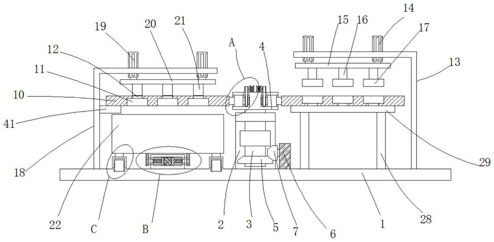
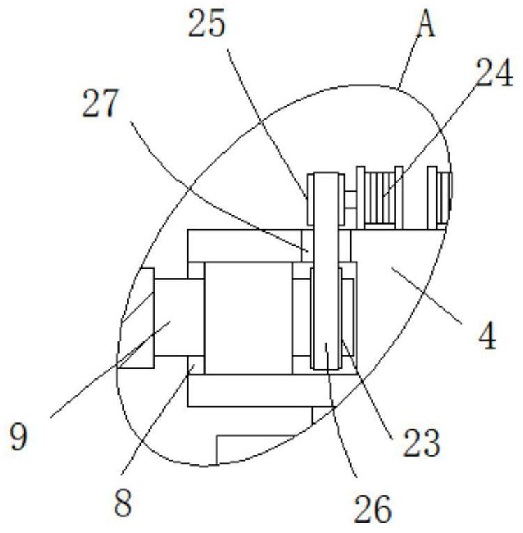
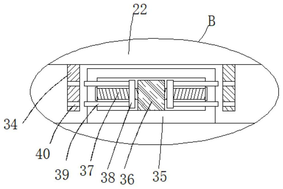
[0030] see Figure 1-7 , a stamping device for the manufacture of electronic vacuum devices, including a base 1, a U-shaped fixing plate 2 is fixedly arranged at the center of the upper end of the base 1, and the inside of the U-shaped fixing plate 2 is rotatably socketed with a column 3 through a ball bearing. The upper end runs through the upper end of the U-shaped fixed plate 2 and is fixedly connected with a fixed block 4, the lower end of the column 3 is fixedly sleeved with a driven bevel gear 5, the upper end of the base 1 is...


PUM


Abstract

The invention relates to the technical field of electronic vacuum device manufacturing, and discloses a stamping device for electronic vacuum device manufacturing, which comprises a base, a U-shaped fixing plate is fixedly arranged at the center of the upper end of the base, and a stand column is rotatably sleeved in the U-shaped fixing plate through a ball bearing; the upper end of the stand column penetrates through the upper end of the U-shaped fixing plate and is fixedly connected with a fixing block, the column wall of the lower end of the stand column is fixedly sleeved with a driven bevel gear, a rotating motor is fixedly arranged at the upper end of the base, an output shaft of the rotating motor is fixedly connected with a driving bevel gear meshed with the driven bevel gear, and grooves are formed in the two opposite sides of the fixing block. A rotating shaft is rotationally sleeved with the groove through the bearing, and one end of the rotating shaft extends out of the fixing block and is fixedly connected with stamping plates. The stamping device for manufacturing the electronic vacuum device has the advantages that rapid discharging operation can be achieved, relative continuous stamping operation can be achieved through the arrangement of the two stamping plates, and the stamping efficiency is greatly improved.

Description

technical field [0001] The invention relates to the technical field of manufacturing electronic vacuum devices, in particular to a stamping device for manufacturing electronic vacuum devices. Background technique [0002] In the production process of electronic stamping parts, stamping equipment needs to be used to stamp them. [0003] The current stamping equipment requires manual blanking and loading after the stamping is completed. Stamping production cannot be carried out during the process of loading and unloading, which greatly affects the stamping efficiency. It is easy to stick in the mold groove, which brings inconvenience to the processing and production of electronic devices. Contents of the invention [0004] (1) Solved technical problems [0005] Aiming at the deficiencies of the prior art, the present invention provides a stamping device for the manufacture of electronic vacuum devices, which can realize fast blanking operation, and the arrangement of two s...

Claims


Application Information

Patent Timeline
Patent Type & Authority Applications(China)
IPC IPC(8): B21D22/08B21D37/14B21D45/02B21D43/20
CPCB21D22/08B21D37/142B21D45/02B21D43/20
Inventor 刘东升曾奎付红陈永
Owner 怀化华晨电子科技有限公司
Why Eureka
Try Eureka