Raindrop sensor

A raindrop sensor and frame cover technology, applied in the field of sensors, can solve problems such as windows being closed

Pending Publication Date: 2022-02-22
宁惠贤
0 Cites 0 Cited by

AI-Extracted Technical Summary

Problems solved by technology

[0003] Although the raindrop sensing module used in the existing automation technology for windows can respond to closing the window in time when it rains, i...

Abstract

The inventin discloses a raindrop sensor. The raindrop sensor comprises a lattice-shaped frame cover, a circuit board of a strip-shaped circuit line in the frame cover, a compression spring and a water absorption plate on a lower side face of the frame cover. The raindrop sensor is advantaged in that a raindrop switch-on electric signal can be well sensed in rainy days, and the electric signal can be timely switched off when the rain stops.

Application Domain

Power-operated mechanismWater resource assessment +2

Technology Topic

MeteorologyAtmospheric sciences +2

Image

  • Raindrop sensor
  • Raindrop sensor
  • Raindrop sensor

Examples

  • Experimental program(1)

Example Embodiment

[0017] Example
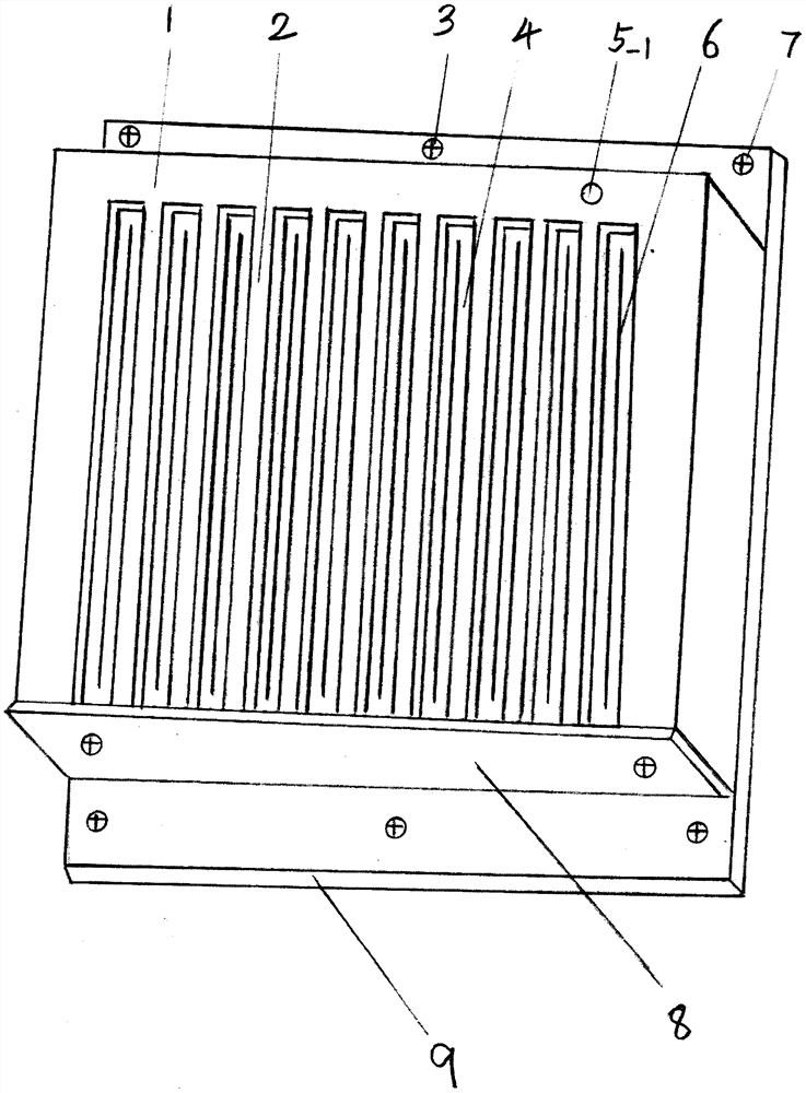
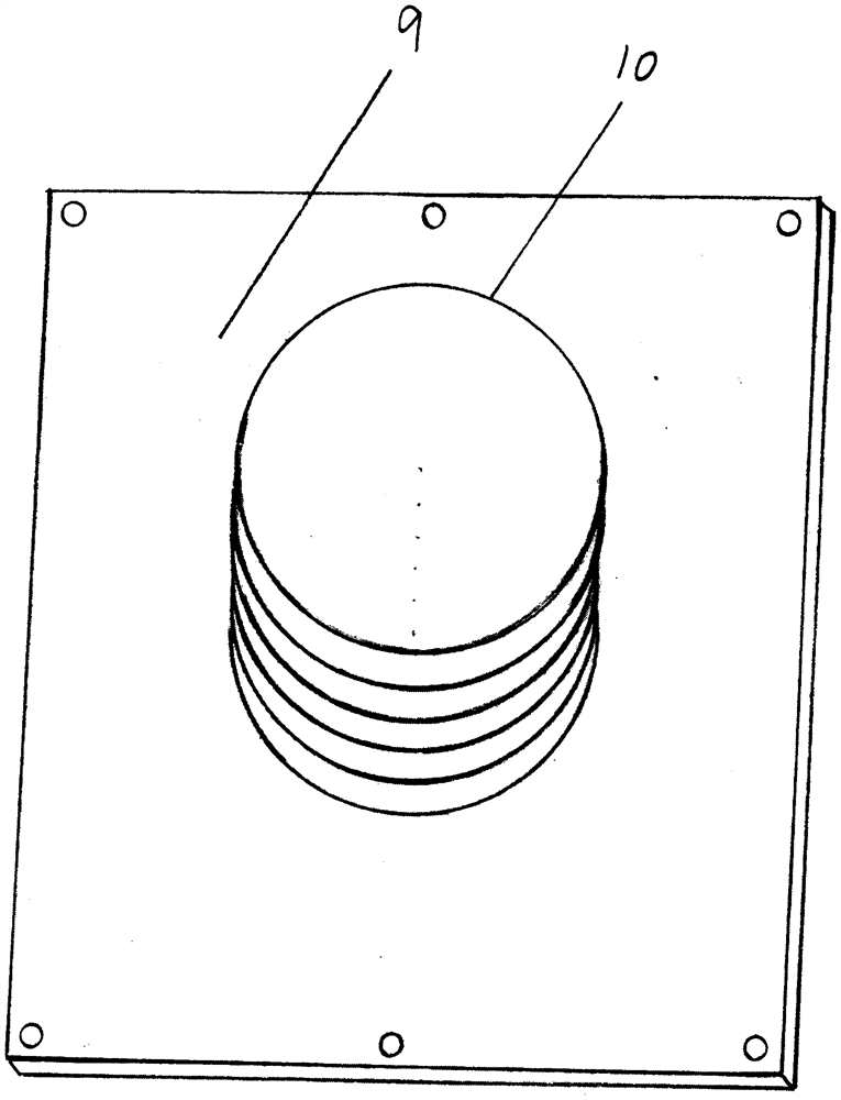
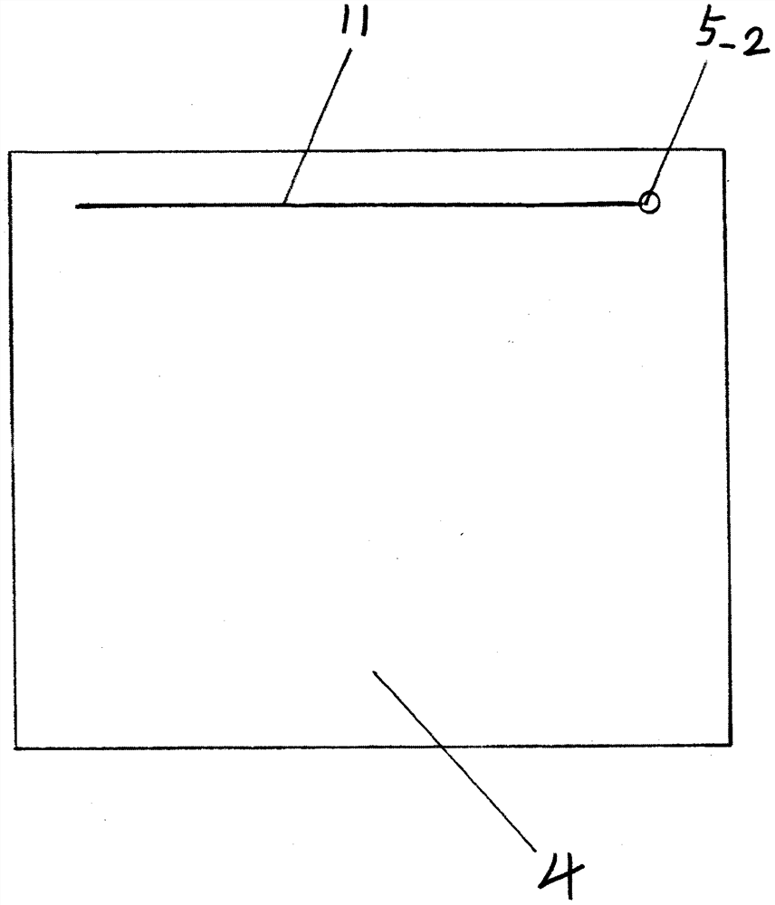
[0018] Refer to attached figure 1 , attached figure 2 , attached image 3 , a raindrop sensor according to the present invention, the circuit board 4 is supported and placed on the bottom surface of the frame strip 2 of the frame cover 1 by a compression spring 10, one end of the compression spring 10 is placed at the center of the bottom plate 9, and the other end is supported on the circuit board 4. At the center of the lower surface of the board 4, each vertical circuit line 6 on the upper surface of the circuit board 4 and each vertical frame bar 2 of the frame cover 1 are evenly combined and placed at an interval of 1.0-1.5mm. In the middle position of each vertical elongated slit, the upper end of each vertical circuit wire 6 turns to pass through the circuit board 4 and electrically connects with the horizontal circuit wire 11 on the lower surface of the circuit board 4 . The right end of the transverse circuit line 11 on the upper part of the lower plate is provided with a connection terminal 5-2. The lower side of the frame cover 1 is provided with a water-absorbing plate 8 . The frame cover 1 is made of conductive material, and the upper part of the frame cover 1 is provided with a connection terminal 5-1. The frame cover 1 is fixed on the bottom plate 9 by screws 7 .
[0019] Working principle and process:
[0020] The present invention can sense raindrops, mainly relying on the raindrops to connect the frame strips 2 of the frame cover 1 and the circuit wires 6 on the circuit board 4 to connect electrical signals; The gap formed by the contact between the upper surfaces of the circuit board 4 absorbs the raindrops connected between the circuit wire 6 and the frame bar 2, and flows down the lower end of the frame bar 2, passing through the gap formed between the water-absorbing plate 8 and the lower side of the frame cover. The cracks further suck the water away, thus disconnecting the electrical signal.

PUM

no PUM

Description & Claims & Application Information

We can also present the details of the Description, Claims and Application information to help users get a comprehensive understanding of the technical details of the patent, such as background art, summary of invention, brief description of drawings, description of embodiments, and other original content. On the other hand, users can also determine the specific scope of protection of the technology through the list of claims; as well as understand the changes in the life cycle of the technology with the presentation of the patent timeline. Login to view more.
Why Eureka
Try Eureka