Laminated piezoelectric element
A piezoelectric element, laminated technology, applied in the direction of electrical components, piezoelectric/electrostrictive/magnetostrictive devices, circuits, etc., can solve the problem of reduced polarization, high resistance value, and resistance value change of the resistance layer And other issues
- Summary
- Abstract
- Description
- Claims
- Application Information
AI Technical Summary
Problems solved by technology
Method used
Image
Examples
no. 1 approach
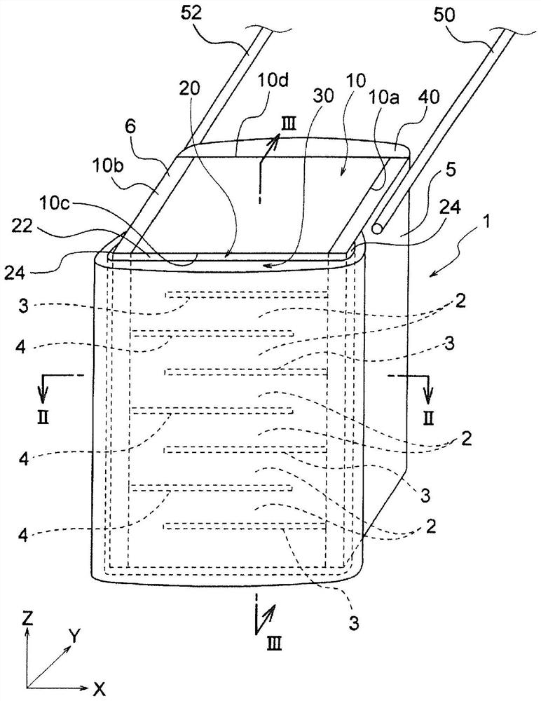
[0051] Such as figure 1 As shown, the multi-layer piezoelectric element 1 of the present embodiment has an element body 10 in the shape of a quadrangular prism. Inside the element main body 10 , the first internal electrode 3 , the piezoelectric layer 2 , and the second internal electrode 4 having a polarity different from that of the first internal electrode 3 are repeatedly laminated along the Z-axis direction (stacking direction). In addition, in the drawings, the X axis, the Y axis, and the Z axis are perpendicular to each other, and the Z axis coincides with the stacking direction.
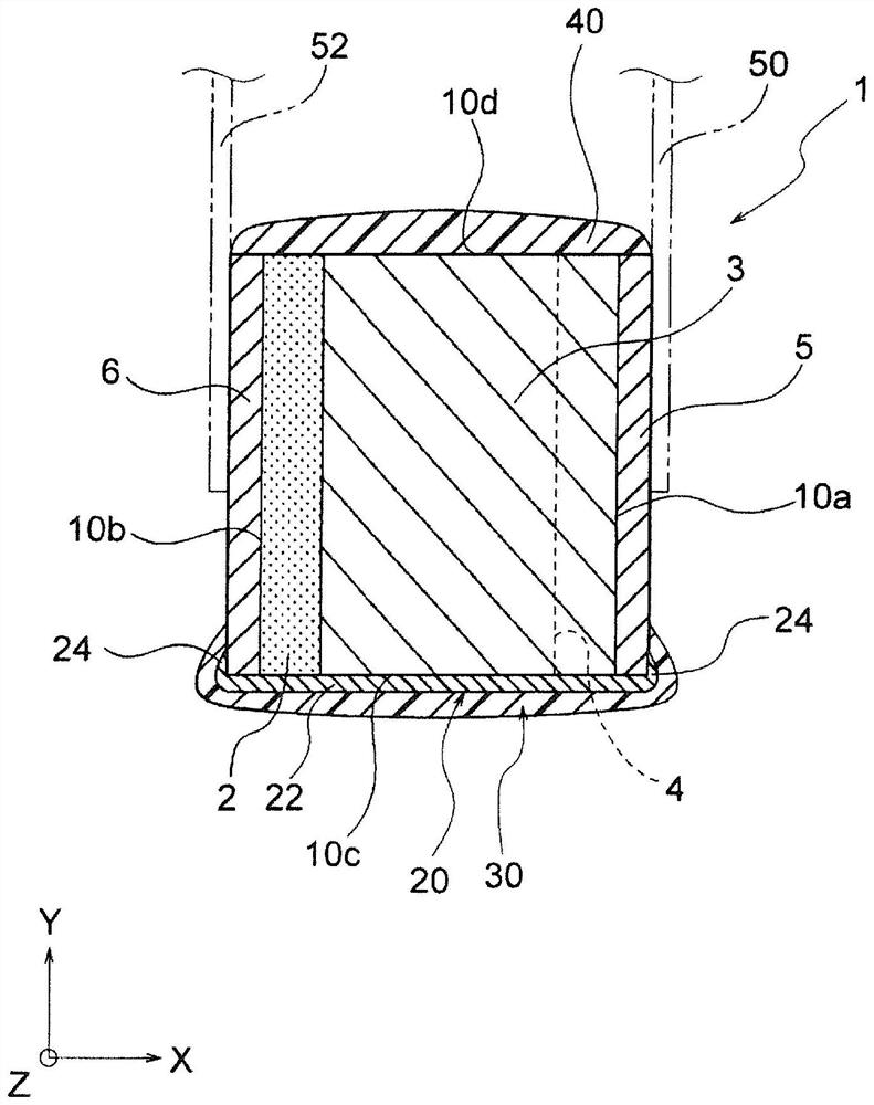
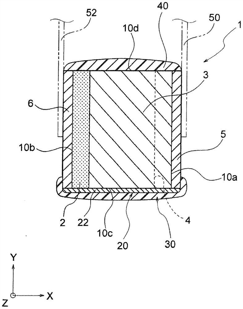
[0052] Such as Figure 2A As shown, on the first side surface 10 a of the element main body 10 , the front ends of the first internal electrodes 3 in the X-axis direction are exposed, and the first external electrodes 5 are formed so as to be electrically connected to these first internal electrodes 3 . Further, on the second side surface 10 b of the element body 10 , the tips of the second...
no. 2 approach
[0091] Such as Figure 4 and Figure 5 As shown, the multilayer piezoelectric element 1a of this embodiment is the same as the multilayer piezoelectric element 1 of the above-mentioned first embodiment except for the following, and the common components are given common symbols and the common parts are omitted. illustrate.
[0092] In this embodiment, unlike the first embodiment, the resistive layer is not formed so as to cover the entire surface of the third side surface 10c of the element body 10, but is formed to cover only both sides of the third side surface 10c in the X-axis direction. Resistive layer 20a. In this embodiment, the resistance layer 20a formed on the third side surface 10c has a pair of vertical continuous portions 22a, 22a, and extension portions 24a, 24a are integrally formed in each vertical continuous portion 22a, 22a, respectively.
[0093] A longitudinal continuous portion 22a extends in stripes along the Z axis, so that the front end of the first ...
no. 3 approach
[0100] Such as Figure 6 and Figure 7 As shown, the multi-layer piezoelectric element 1b of this embodiment is the same as the multi-layer piezoelectric element 1a of the above-mentioned second embodiment except for the following, and common components are given common symbols and common parts are omitted. instruction of.
[0101] In this embodiment, the resistive layer 20b is composed of at least one pair of longitudinal continuous portions 22b and at least one transverse continuous portion 26b. It is also possible to form an extension portion 24b in each longitudinal continuous portion 22b.
[0102] In this embodiment, unlike the second embodiment, stripe-shaped longitudinal continuous portions 22b formed on both sides in the X-axis direction of the third side surface 10c of the element body 10 are integrally connected by at least one transverse continuous portion 26b. In the present embodiment, the two ends of the pair of vertical continuous portions 22b in the Z-axis d...
PUM
| Property | Measurement | Unit |
|---|---|---|
| thickness | aaaaa | aaaaa |
| thickness | aaaaa | aaaaa |
| thickness | aaaaa | aaaaa |
Abstract
Description
Claims
Application Information
 - R&D
- Intellectual Property
- Life Sciences
- Materials
- Tech Scout
- Unparalleled Data Quality
- Higher Quality Content
- 60% Fewer Hallucinations
Browse by: Latest US Patents, China's latest patents, Technical Efficacy Thesaurus, Application Domain, Technology Topic, Popular Technical Reports.
© 2025 PatSnap. All rights reserved.Legal|Privacy policy|Modern Slavery Act Transparency Statement|Sitemap|About US| Contact US: help@patsnap.com


