Mobile phone rear shell polishing and grinding device
A technology of mobile phone rear shell and mounting frame, which is applied in the direction of grinding drive device, grinding machine, grinding feed motion, etc., can solve the problem of low polishing efficiency of mobile phone rear shell, achieve high market application value, reduce work intensity, Avoid effects with a high degree of manual intervention
- Summary
- Abstract
- Description
- Claims
- Application Information
AI Technical Summary
Problems solved by technology
Method used
Image
Examples
specific Embodiment 1
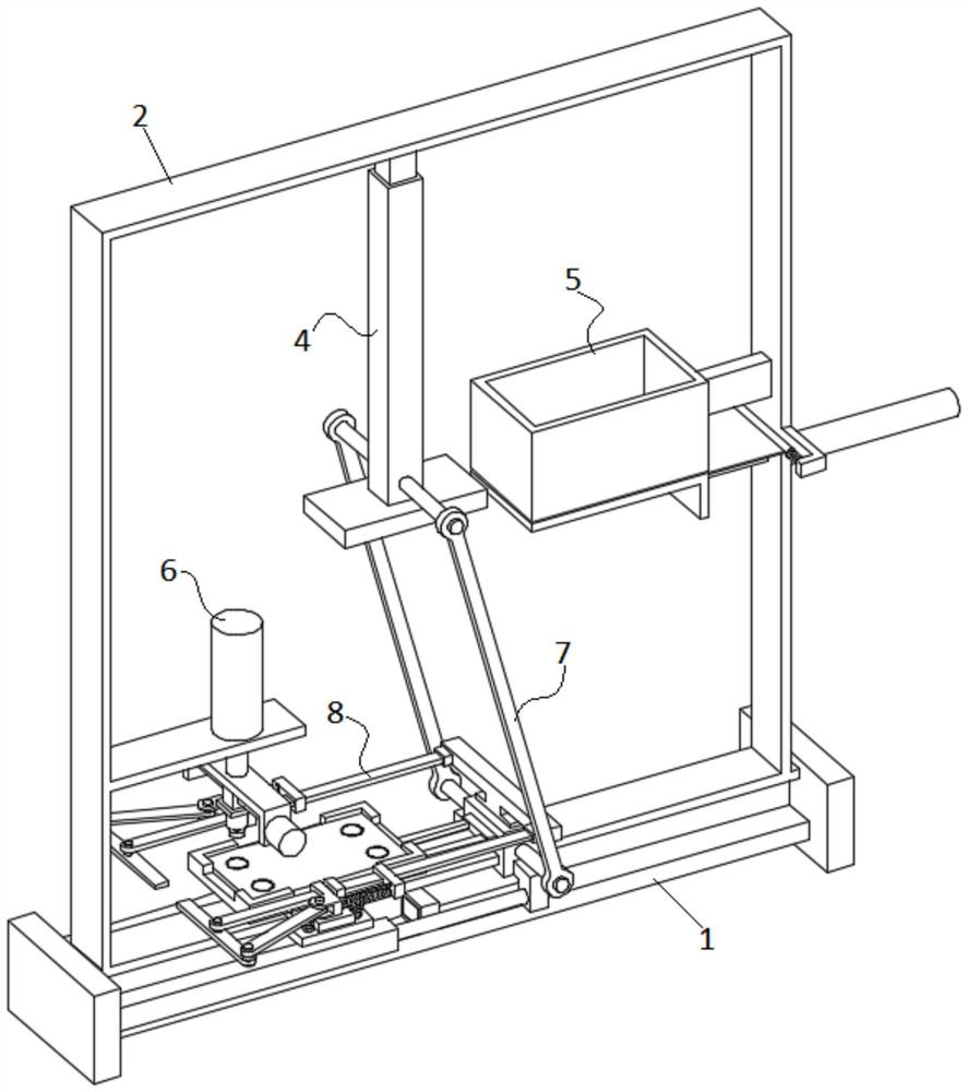
[0031] see figure 1As shown, the present invention is a polishing device for the back shell of a mobile phone, which includes a horizontally arranged support rail 1; A mounting frame 2 with a "ㄇ" structure; the two ends of the mounting frame 2 are respectively fixed on the two ends of the support rail 1; a load-bearing component 3 is installed on the support rail 1; a conveying component 4 is installed above the load-bearing component 3 ; The opposite sides of the feeding assembly 4 are respectively equipped with a feeding assembly 5 and a polishing assembly 6; A mobile phone back shell is sent to the feeding assembly 4 through the feeding assembly 5 , and then the mobile phone back shell is sent to the carrying assembly 3 through the feeding assembly 4 , and finally the mobile phone back shell is polished through the polishing assembly 6 .
specific Embodiment 2
[0033] This embodiment is further optimized on the basis of specific embodiment one, specifically as follows:
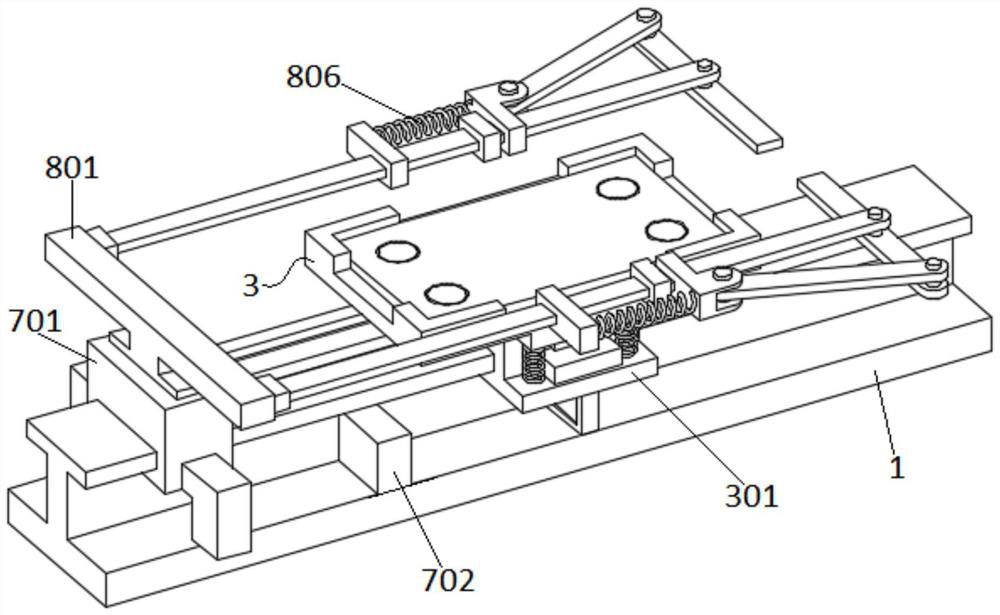
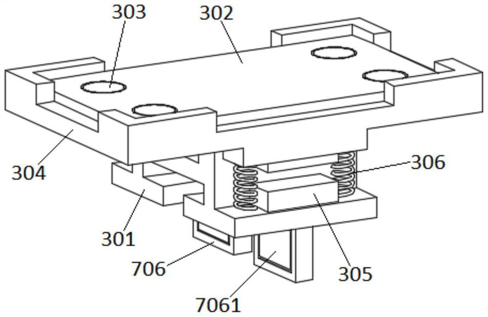
[0034] Such as Figure 1-4 As shown, the bearing assembly 3 includes a first slider 301 that is slidably connected to the support rail 1; the upper surface of the first slider 301 is horizontally fixed with a bearing platform 302 for placing the rear shell of the mobile phone; the upper surface size of the bearing platform 302 The size is consistent with the size of the back shell of the mobile phone; the upper surface of the carrying platform 302 is embedded with a plurality of first suction cups 303 side by side; the first suction cups 303 adopt conventional electric vacuum suction cups in the field; Position frame 304; the inner surface of the limit frame 304 fits the outer surface of the bearing platform 302; the upper surface of the limit frame 304 is evenly distributed and integrally formed with a plurality of limit protrusions for limiting the position of the ...
specific Embodiment 3
[0036] This embodiment is further optimized on the basis of specific embodiment two, specifically as follows:
[0037] Such as figure 1 and Figure 5 As shown, the feeding assembly 4 includes a guide column 401 vertically fixed on the middle section of the installation frame 2; a sliding sleeve 402 is provided on the guide column 401; a feeding plate 403 is fixed horizontally at the lower end of the sliding sleeve 402; A plurality of second suction cups 404 are uniformly embedded in the lower surface of the plate 403; the second suction cups 404 adopt conventional electric vacuum suction cups in the field. The second suction cup 404 is used to absorb a mobile phone rear case from the feeding assembly 5 , and then the sliding sleeve 402 is used to drive the feeding plate 403 to move downward, thereby sending the mobile phone rear case to the carrying platform 302 .
PUM
 Abstract
Description
Claims
Application Information
 - R&D
- Intellectual Property
- Life Sciences
- Materials
- Tech Scout
- Unparalleled Data Quality
- Higher Quality Content
- 60% Fewer Hallucinations
Browse by: Latest US Patents, China's latest patents, Technical Efficacy Thesaurus, Application Domain, Technology Topic, Popular Technical Reports.
© 2025 PatSnap. All rights reserved.Legal|Privacy policy|Modern Slavery Act Transparency Statement|Sitemap|About US| Contact US: help@patsnap.com


