Eureka AIR delivers breakthrough ideas for toughest innovation challenges, trusted by R&D personnel around the world.

A feeder hole polishing device and method

A technology of polishing device and feeder, which is applied in the direction of grinding/polishing safety device, grinding drive device, grinding/polishing equipment, etc., which can solve the difficulty in meeting the performance requirements of the antenna vibrator, the difficulty in solving the vibration of the end of the polishing rod, and the decline in polishing accuracy To achieve the effect of ensuring polishing stability, reasonable and ingenious structural design, and improving polishing accuracy

Active Publication Date: 2021-12-07
东莞市振亮精密科技有限公司
View PDF0 Cites 0 Cited by
  • Summary
  • Abstract
  • Description
  • Claims
  • Application Information

AI Technical Summary

Problems solved by technology

[0004] In the production process of the antenna vibrator, the polishing of the feed line hole and the polishing of the vibrator sheet have a great influence on the performance of the antenna vibrator; but in the polishing process of the feed line hole, since the feed line hole is not in the center of the antenna vibrator , to deal with the polishing and grinding that needs to shift the center of rotation, the existing technology does not have a good solution. Generally, a multi-degree-of-freedom manipulator is used to drive the polishing rod to rotate and grind. On the one hand, the processing efficiency of this method is low, and the high-precision control makes the cost On the other hand, it is difficult to solve the vibration of the end of the polishing rod, resulting in a decrease in the precision of the polishing, and it is difficult to meet the performance requirements of the antenna vibrator

Method used


Image

  • A feeder hole polishing device and method
  • A feeder hole polishing device and method
  • A feeder hole polishing device and method

Examples


Embodiment Construction

[0055] In order to make the above objects, features and advantages of the present invention more comprehensible, specific implementations of the present invention will be described in detail below in conjunction with the accompanying drawings. In the following description, numerous specific details are set forth in order to provide a thorough understanding of the present invention. However, the present invention can be implemented in many other ways different from those described here, and those skilled in the art can make similar improvements without departing from the connotation of the present invention, so the present invention is not limited by the specific embodiments disclosed below.

[0056] In describing the present invention, it is to be understood that the terms "upper", "lower", "front", "rear", "left", "right", "vertical", "horizontal", "top", The orientation or positional relationship indicated by "bottom", "inner", "outer", etc. is based on the orientation or po...


PUM


Abstract

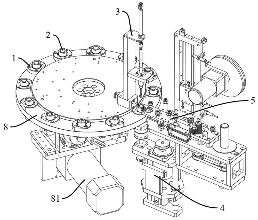
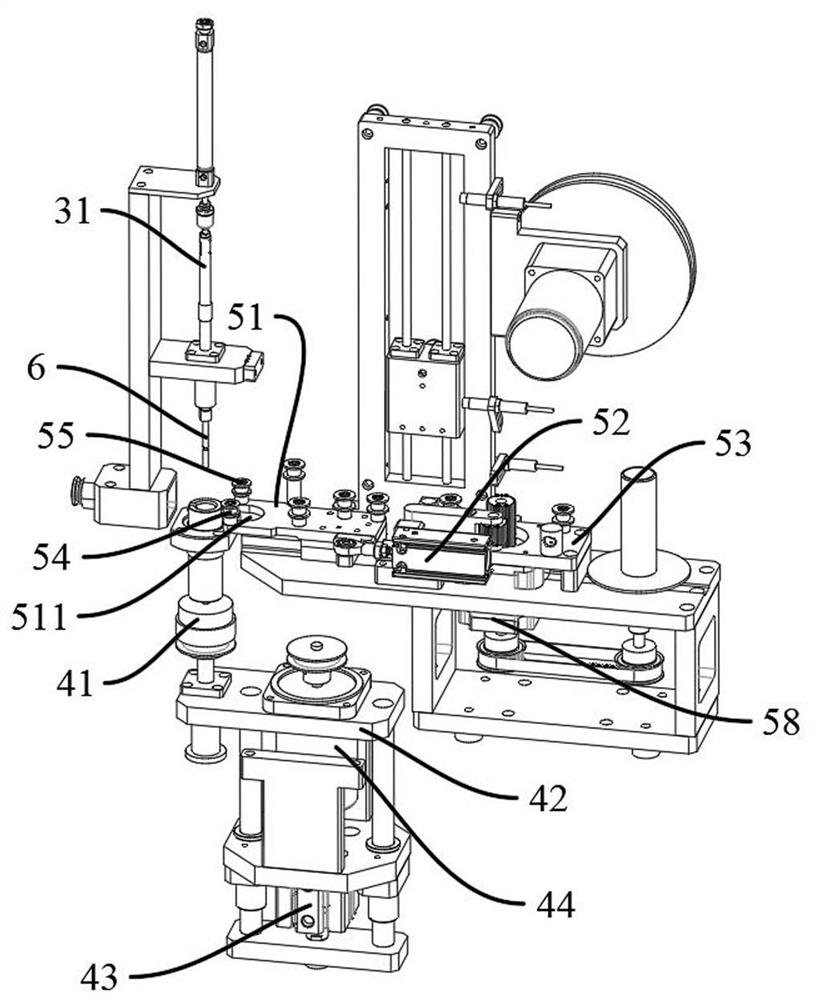
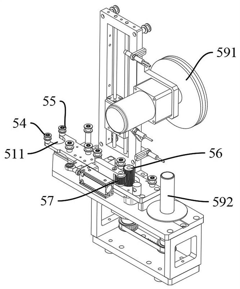
The invention discloses a feeder hole polishing device and method, wherein the feeder hole polishing device includes: a base, which has an accommodating space; Place the antenna vibrator; the polishing rod supply assembly, which is used to supply the polishing rod to the vibrator fixture; the jig drive assembly, which is located under the vibrator fixture, has a magnet drive block, and the magnet drive block is provided with a rotation positioning groove; Wherein, the lower end of the vibrator jig is extended with a magnet coupling part protruding from the lower end surface of the base, and the jig drive assembly drives the magnet coupling part to rotate through the magnet drive block; the polishing rod passes through the feeder hole of the antenna vibrator and is inserted into the rotation positioning slot to determine The center of rotation of the magnet joint. The automatic polishing of the feeder hole is realized, which solves the problem that the prior art does not have a good solution for the polishing that needs to be shifted from the center of rotation, and the problem of the drop in polishing accuracy caused by the vibration of the end of the polishing rod during processing.

Description

technical field [0001] The invention relates to the field of antenna vibrator processing, in particular to a feeder hole polishing device and method. Background technique [0002] The AAU (Active Antenna Processing Unit) for 5G base stations mainly includes Massive MIMO antennas (large-scale antennas), filters, active components, etc. Antenna dipoles are most popular with dual-polarized antenna dipoles; Antenna oscillators also make their specifications emerge in endlessly. How to realize high-speed production of economical antenna oscillators is an important factor for the high cost and difficulty of popularizing 5G base stations at this stage. [0003] In the process of realizing the technical solution of the invention in the embodiment of the present application, the inventor of the present application found that the above-mentioned technology has at least the following technical problems: [0004] In the production process of the antenna vibrator, the polishing of the f...

Claims


Application Information

Patent Timeline
Patent Type & Authority Patents(China)
IPC IPC(8): B24B29/02B24B41/06B24B41/00B24B21/18B24B21/00B24B27/00B24B47/06B24B55/00
CPCB24B21/006B24B21/008B24B21/18B24B27/0076B24B29/02B24B41/005B24B41/06B24B47/06B24B55/00
Inventor 陈文陈洪胜高浩哲郭新建李鹏辉
Owner 东莞市振亮精密科技有限公司
Why Eureka
Eureka Blog
Learn More