

Quenching and cooling device
A technology of cooling device and quenching tank, which is applied in the field of quenching and cooling, can solve the problems of uncontrolled cooling process, collision and confusion of workpieces, etc., and achieve the effect of improving product heat treatment quality, fast cooling speed and uniform cooling
- Summary
- Abstract
- Description
- Claims
- Application Information
AI Technical Summary
Problems solved by technology
Method used
Image

Examples
Embodiment
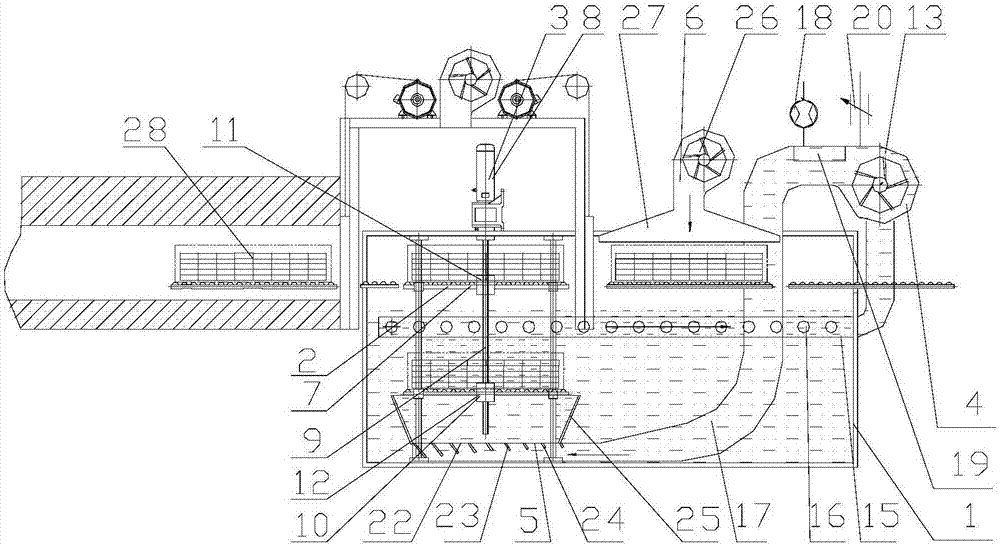
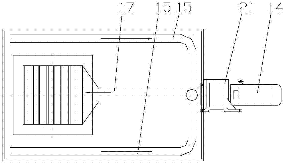
[0017]The main structure of the quenching and cooling device involved in this embodiment includes: quenching tank 1, quenching platform 2, quenching platform lifting system 3, medium circulation system 4, medium outlet system 5, medium blowing system 6, cooling zone roller 7, Power motor 8, lead screw 9, nut 10, guide sleeve 11, guide rail 12, circulation pump 13, frequency conversion motor 14, liquid suction pipeline 15, liquid suction port 16, liquid outlet pipeline 17, electronic flowmeter 18, cooler 19. Electric control valve 20, flow controller 21, medium outlet 22, deflector 23, blade 24, shroud 25, fan 26 and wind cover 27; quenching tank 1 is a container with an open top, located in the cooling zone of the quenching production line In the lower part, the quenching table 2 includes a cooling zone roller 7 and a nut 10, and the cooling zone roller 7 and the nut 10 are fixedly connected together; the quenching platform lifting system 3 includes a power motor 8, a lead scre...
Embodiment 2
[0020] The power motor 8 of the quenching platform lifting system 3 is preferably a servo motor, and the rotation of the motor can be precisely controlled by the encoder of the servo motor, thereby accurately controlling the position of the quenching platform 2 in the quenching tank 1 .
PUM
 Abstract
Description
Claims
Application Information