A double-sided polishing equipment

A double-sided polishing and equipment technology, which is applied in the direction of grinding/polishing equipment, surface polishing machine tools, metal processing equipment, etc., can solve the problems of finger injuries, waste, and difficult handling of experimental operators, and achieve small batches, structure Simple, easy-to-handle effects

Active Publication Date: 2018-06-22
广西日瑞智能科技有限公司
View PDF6 Cites 0 Cited by
  • Summary
  • Abstract
  • Description
  • Claims
  • Application Information

AI Technical Summary

Problems solved by technology

[0002] At present, college laboratories often use manual polishing when trial-manufacturing ceramic samples. This processing method is easy to injure the fingers of the operator due to the thin ceramic sheets (about 1-2mm)
In addition, the grinding thickness of the ceramic sheet is not easy to control. If the grinding is too thin, the surface processing quality will not affect the performance test of the ceramic sheet. If the grinding is too thick, the ceramic sheet is too thin and fragile.
For the polishing of campuses and laboratories on-the-go, small batches, and small workpieces, it would be particularly wasteful to use an expensive CNC and high-efficiency polishing equipment, and it is not easy to carry
If ordinary manual polishing equipment is used, it is difficult to meet the polishing requirements, and there are various safety hazards. Manual polishing may easily cause finger injuries to experimental operators, and the product qualification rate is low.

Method used


Image

  • A double-sided polishing equipment
  • A double-sided polishing equipment
  • A double-sided polishing equipment

Examples


Embodiment Construction

[0036] The specific implementation of the invention will be further described below in conjunction with the accompanying drawings.

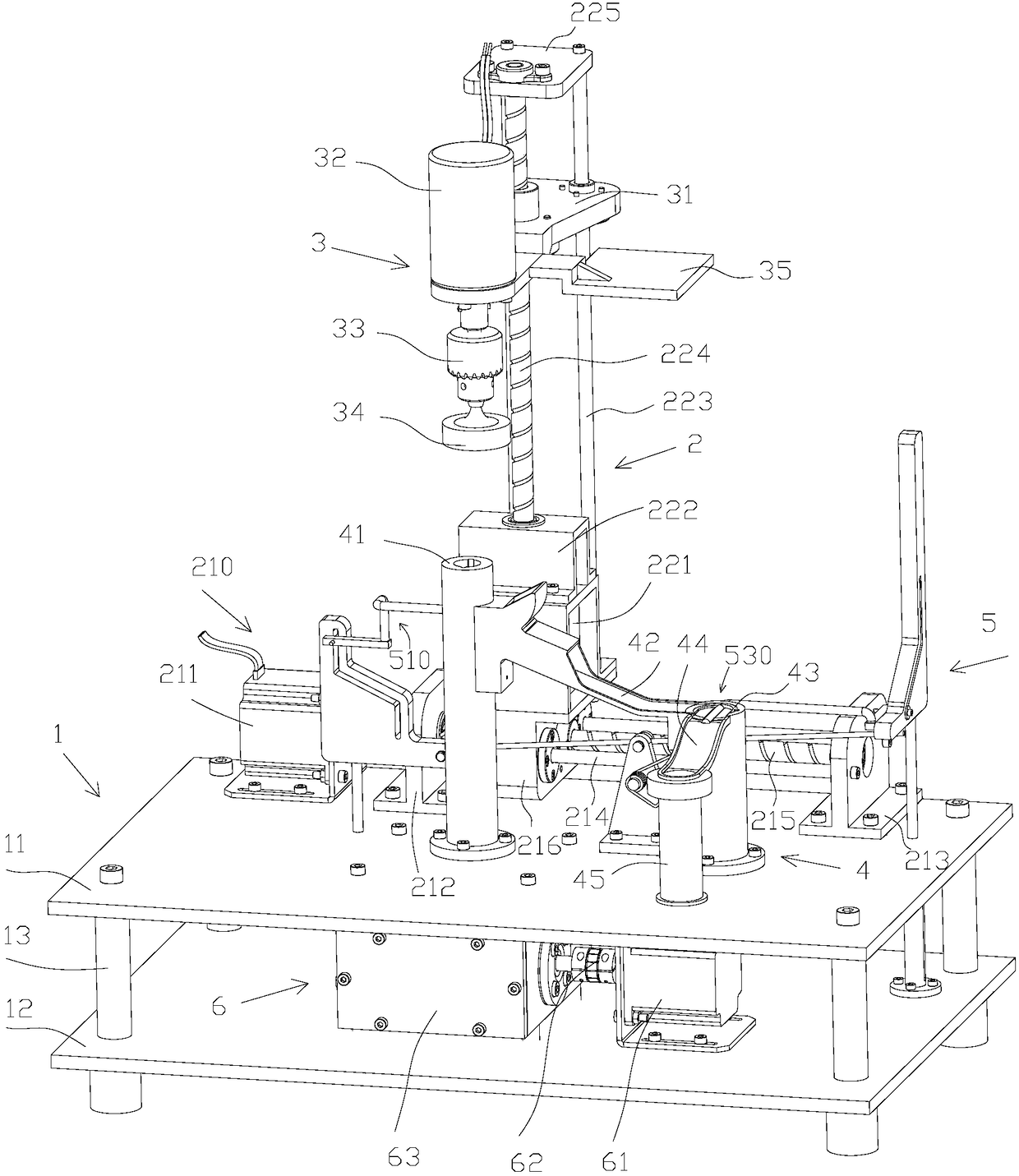
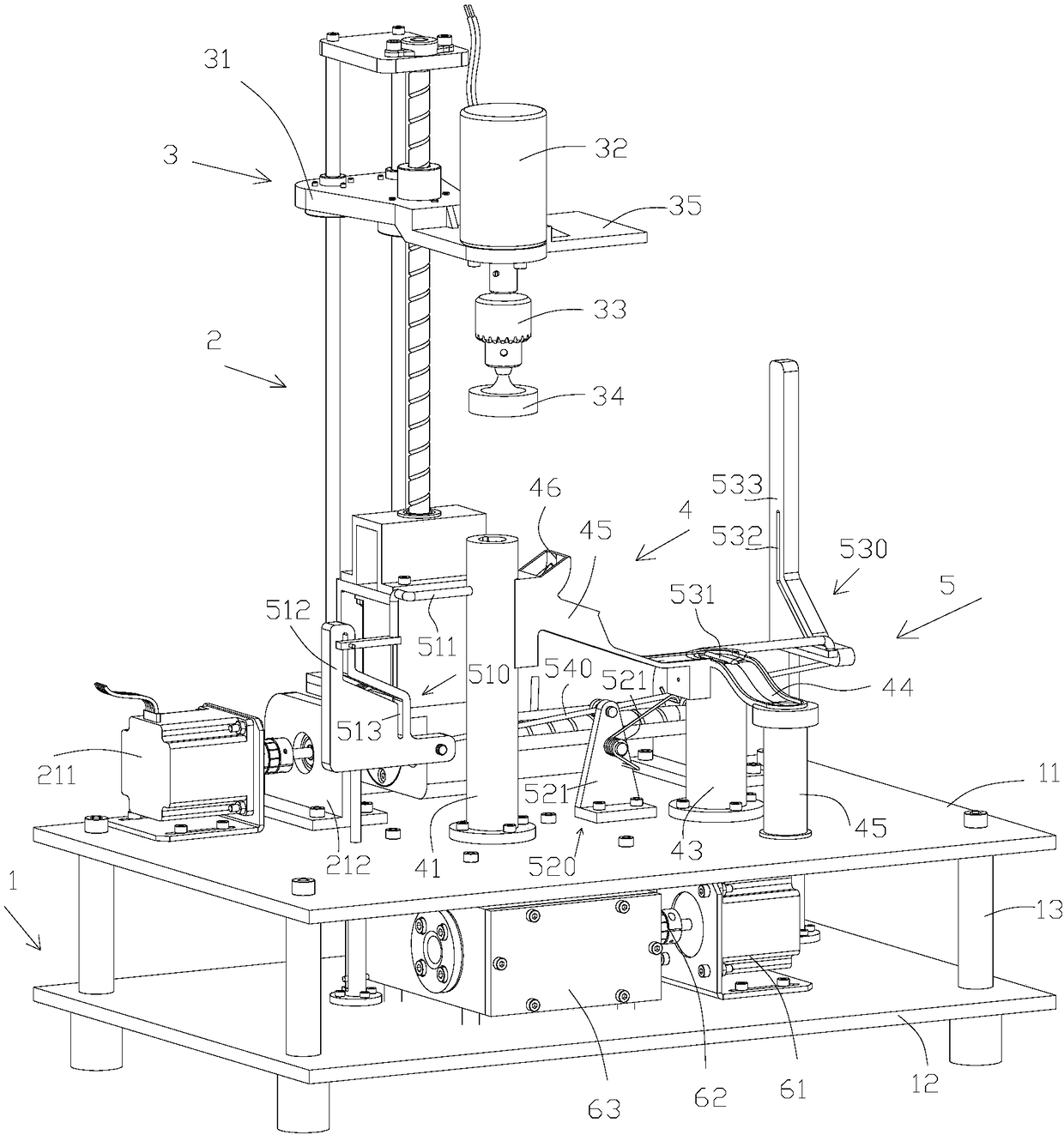
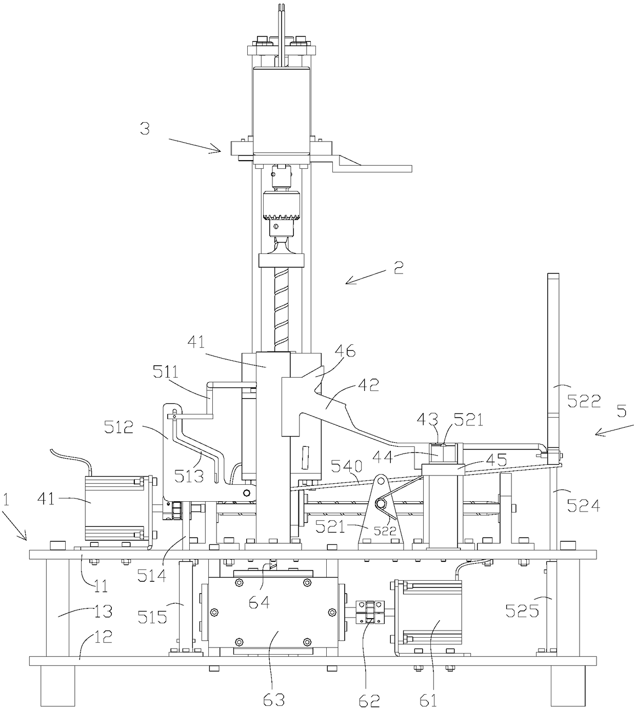
[0037] Such as Figure 1-5 As shown, a preferred embodiment is disclosed. The double-sided polishing equipment includes a base 1, a mobile platform 2 installed on the upper end surface of the base 1, a polishing assembly 3 installed on the mobile platform 2, and a workpiece placement table assembly 4 installed on the upper end surface of the base 1 and corresponding to the polishing assembly 3. The mobile platform 2 includes a first mobile mechanism 210 for lateral movement, and a second mobile mechanism 220 mounted on the first mobile mechanism 210 for longitudinal movement, and the second mobile mechanism 220 is driven by the first mobile mechanism 210 to move laterally. The polishing assembly 3 includes a lifting platform 31 installed on the second moving mechanism 220 and driven by the second moving mechanism 220 to move longitudinally, a po...


PUM


Abstract

The invention discloses double-sided polishing equipment, and belongs to the field of surface polishing equipment. The double-sided polishing equipment comprises a base, a movable platform installed on the upper end surface of the base, a polishing assembly installed on the movable platform, and a workpiece placement table assembly installed on the upper end surface of the base and corresponding to the polishing assembly, wherein the workpiece placement table assembly comprises a first placement table, a first slide, a second placement table, a second slide and a storage barrel; a turnover part is arranged at the inlet of the first slide and opposite to one side of the first placement table; and a push rod mechanism is further arranged in a manner of corresponding to the first placement table and the second placement table, and a feeding mechanism is arranged in the first placement table. The double-sided polishing equipment disclosed by the invention is small in size, capable of realizing double-sided polishing for a ceramic wafer, and capable of effectively improving the working environment of experimenters and increasing the experiment efficiency.

Description

technical field [0001] The invention relates to the field of surface polishing equipment, in particular to a double-sided polishing equipment. Background technique [0002] At present, college laboratories often use manual polishing when trial-manufacturing ceramic samples. This processing method is easy to injure the fingers of the operator due to the thin ceramic sheets (about 1-2 mm). In addition, the grinding thickness of the ceramic sheet is not easy to control. If the surface is too thin, the surface processing quality will not be good, which will affect the performance test of the ceramic sheet. If the grinding is too thick, the ceramic sheet will be too thin and fragile. For the polishing of campuses and laboratories, small batches, and small workpieces, it would be wasteful to use an expensive CNC and high-efficiency polishing equipment, and it is not easy to carry. If ordinary manual polishing equipment is used, it is difficult to meet the polishing requirements, ...

Claims


Application Information

Patent Timeline
Patent Type & Authority Patents(China)
IPC IPC(8): B24B29/02B24B41/02B24B41/00B24B51/00B24B47/00B24B27/00
CPCB24B27/0023B24B29/02B24B41/005B24B41/02B24B47/00B24B51/00
Inventor 严天祥张烈平黄城志潘思延陶海颖梁胜福梁海罗杰
Owner 广西日瑞智能科技有限公司
Why Eureka
Try Eureka