Fabric gripping device

A technology for grabbing devices and fabrics, which is applied in the direction of manipulators, program-controlled manipulators, chucks, etc., can solve problems such as low production efficiency, time-consuming and laborious, and failed handling, and achieve the effects of low cost, firm gripping of fabrics, and ingenious and compact design

Pending Publication Date: 2022-03-01
厦门市华飚科技有限公司
View PDF0 Cites 0 Cited by
  • Summary
  • Abstract
  • Description
  • Claims
  • Application Information

AI Technical Summary

Problems solved by technology

In the current existing technology, the transfer is carried out manually, which is not only time-consuming and labor-intensive, but also has low production efficiency
In addition, during the transfer process of multi-layer fabrics, sometimes it is necessary to carry one layer of fabric, but due to the characteristics of the fabric itself, it is necessary to carry multiple layers of fabric at one time, which makes the transfer fail

Method used


Image

  • Fabric gripping device
  • Fabric gripping device
  • Fabric gripping device

Examples


Embodiment 1

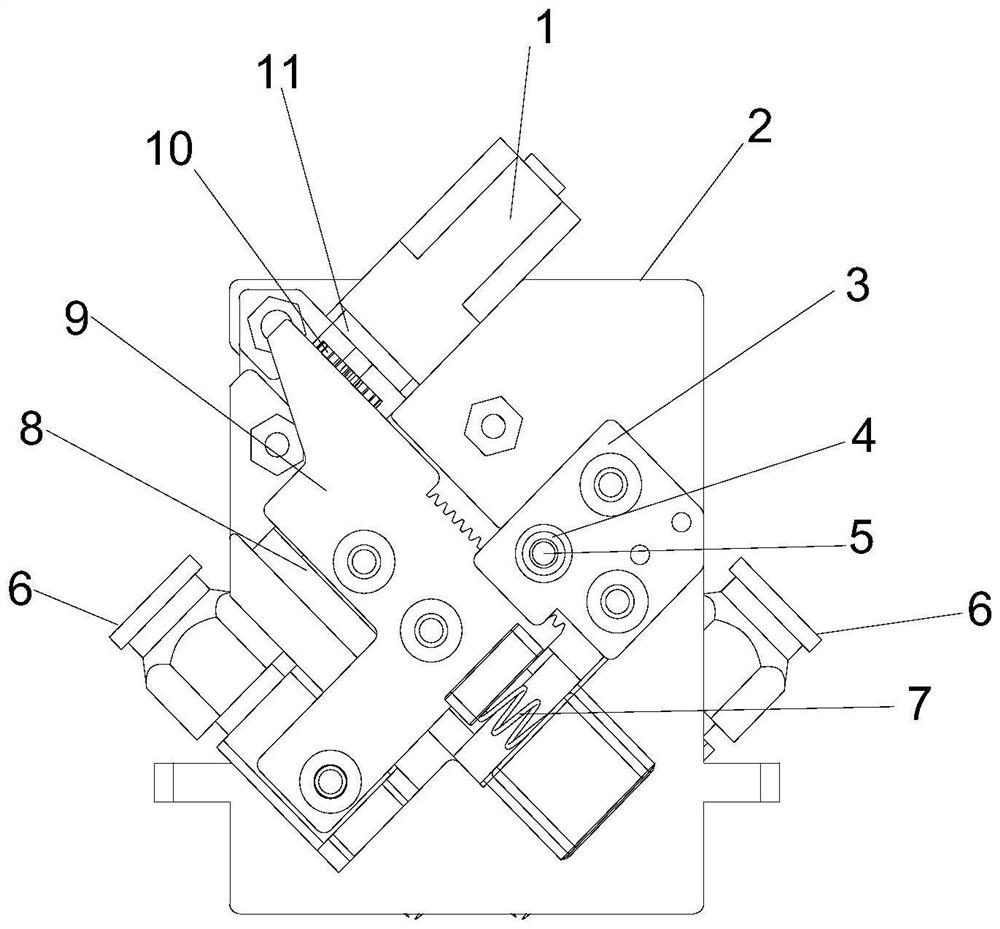
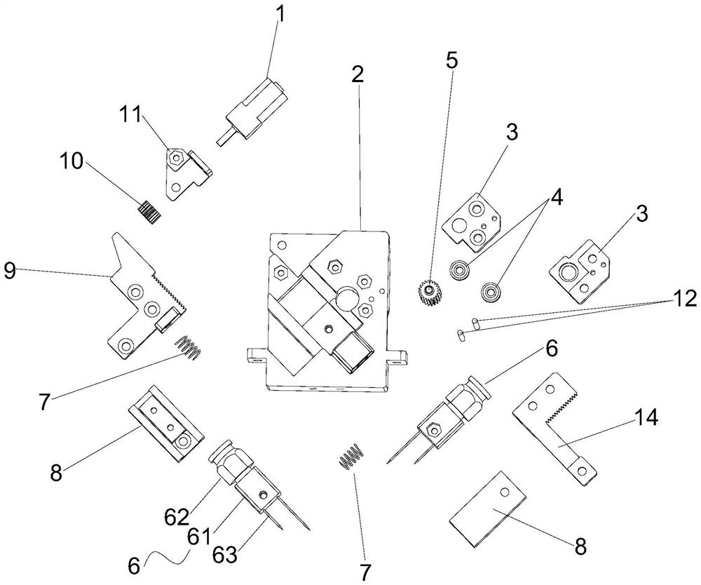
[0032] like Figure 1~4 As shown, the fabric grabbing device of this embodiment includes a fixed seat 2 and a motor 1 located on the fixed seat 2, a gear transmission unit, and two groups of grabbing mechanisms 6;

[0033] Described motor 1 is fixed on the fixed seat 2 by motor fixing plate 11, and the rotating shaft of described motor 1 is provided with rotating gear 10; In the present embodiment, the driving unit adopts motor, and in other embodiments, electromagnet, Driven by electric or pneumatic cylinders;

[0034] The two groups of grasping mechanisms 6 are arranged vertically and intersecting;

[0035] The gear transmission unit includes a first rack 9, a second rack 14 and a reversing gear 5, the first rack 9 is connected with one group of grabbing mechanisms 6, and the second rack 14 is connected with another group The gripping mechanism 6 is connected; the first rack 9 includes a lower rack arranged downward and a side rack arranged sideways, and the rotating gear ...

Embodiment 2

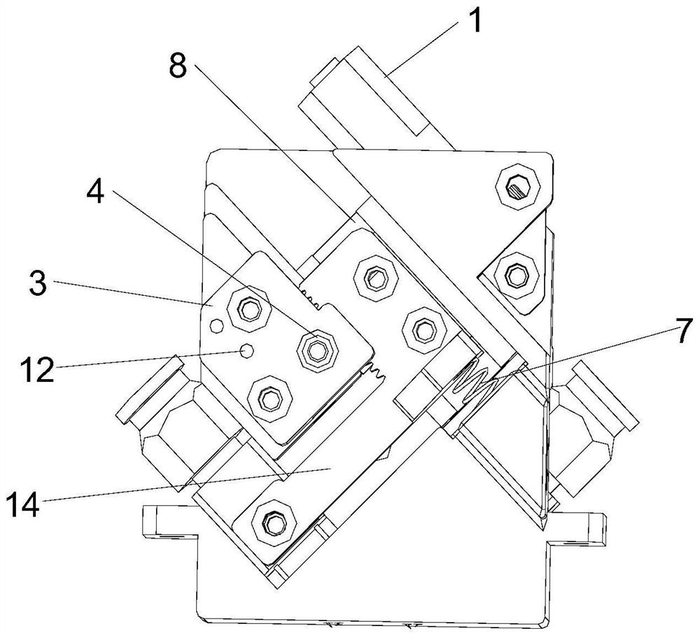
[0049] like Figure 5-8 As shown, the main structure of the fabric grabbing device of this embodiment is similar to that of Embodiment 1, the difference mainly lies in the design of the grabbing mechanism 6 .

[0050] In this embodiment, the gripping mechanism 6 includes a connecting piece 61 and a splint 64, the connecting piece 61 is connected with the first rack 9 or the second rack 14 of the gear transmission unit; 64 front cross contacts to grip the fabric. In this embodiment, each group of gripping mechanisms 6 is provided with two groups of splints 64 with different lengths, and the front ends of the splints 64 are on the same horizontal plane. Since the splint 64 has a certain cross section, the clamping of the fabric is more firm.

[0051] The installation method of the fabric grabbing device in this embodiment is similar to that in Embodiment 1.

[0052] The working principle of the fabric grabbing device of this embodiment is as follows:

[0053] The motor 1 wor...


PUM


Abstract

The fabric grabbing device comprises a fixed seat, and a driving unit, a gear transmission unit, a first grabbing mechanism and a second grabbing mechanism which are arranged on the fixed seat, the gear transmission unit is connected with the first grabbing mechanism and the second grabbing mechanism, the first grabbing mechanism and the second grabbing mechanism are arranged in a crossed mode, a rotating gear is arranged on a rotating shaft of the driving unit, and the rotating gear and the gear transmission unit act to drive the first grabbing mechanism and the second grabbing mechanism to move to form crossed action. The grabbing device can solve the problem that the fabric cannot be grabbed in the transfer process, is particularly suitable for grabbing porous, breathable and different-shape materials, can also solve the problem that multiple layers of fabric cannot be separated when the fabric is grabbed, and particularly can smoothly layer the fabric with the adhesion characteristic without damaging the fabric.

Description

technical field [0001] The invention relates to the textile field, in particular to a fabric grabbing device. Background technique [0002] Existing fabrics will use multiple sets of equipment for production in the weaving process, therefore, the fabric needs to be transferred from the previous process to the next process. In the current existing technology, the transshipment is performed manually, which is not only time-consuming and laborious, but also has low production efficiency. In addition, during the transfer process of multi-layer fabrics, sometimes it is necessary to carry one layer of fabrics, but due to the characteristics of the fabric itself, multiple layers of fabrics are carried at one time, which makes the transfer fail. Contents of the invention [0003] The purpose of the present invention is to solve the above-mentioned problems in the prior art, and provide a fabric grabbing device, which can effectively move and separate multi-layer fabrics. [0004...

Claims


Application Information

Patent Timeline
IPC IPC(8): B25J9/10B25J15/00
CPCB25J9/102B25J15/0052
Inventor 叶渊庭
Owner 厦门市华飚科技有限公司
Why Eureka
Try Eureka