Corrugated carton flattening assembly

A technology for corrugated boxes and components, applied in the field of corrugated boxes, can solve the problems of poor flattening effect and low efficiency, and achieve the effects of uniform flattening, high efficiency and improved flattening quality.

Inactive Publication Date: 2022-03-01
南京塞拉多科技有限公司
View PDF0 Cites 0 Cited by
  • Summary
  • Abstract
  • Description
  • Claims
  • Application Information

AI Technical Summary

Problems solved by technology

[0004] (1) The technical problem to be solved in the present invention is: the flattening effect is poor, and it needs to manually take materials, and the efficiency is low

Method used


Image

  • Corrugated carton flattening assembly
  • Corrugated carton flattening assembly
  • Corrugated carton flattening assembly

Examples


Embodiment 1

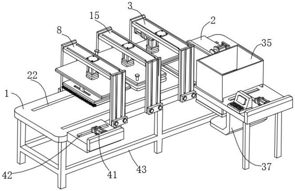
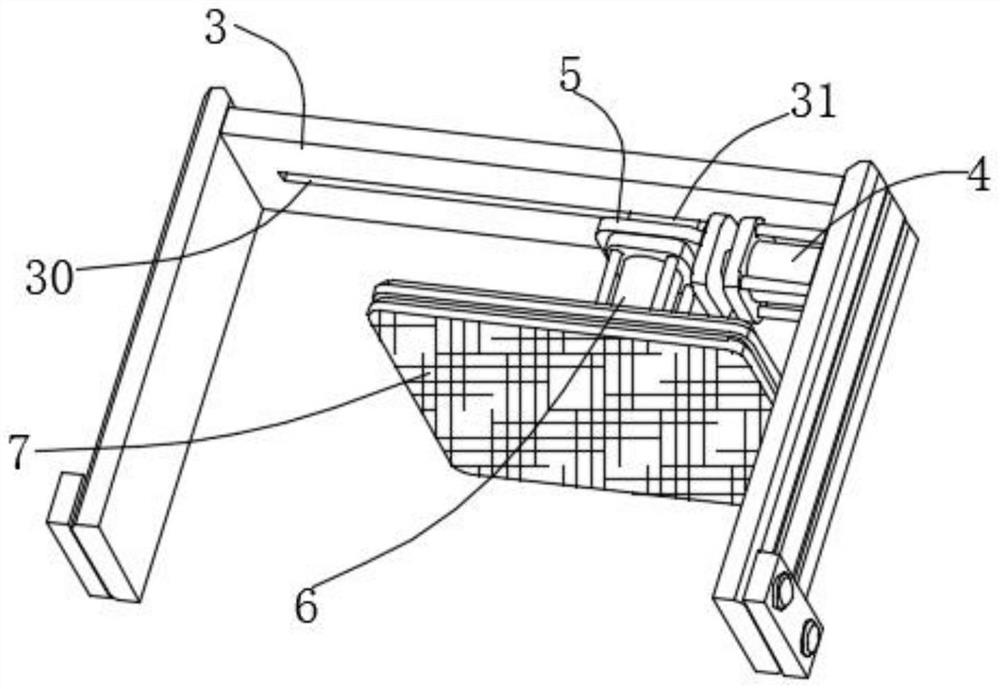
[0033] Such as figure 1 , figure 2 , image 3 , Figure 4 , Figure 5 , Image 6 , Figure 7 , Figure 8As shown, this embodiment proposes a corrugated box flattening assembly, including a horizontally arranged door-shaped table top 1, a console is installed on the upper surface of the table top 1, the console is used to control the electric components, and a base is fixedly installed on the lower end of the table top 1 frame 43, the upper end surface of the table top 1 is horizontally installed with a moving plate 2 through a sliding mechanism, the upper end surface of the moving plate 2 is equipped with a fixing mechanism, and one end of the outer side wall of the moving plate 2 is fixedly installed with a first fixed frame 3, and the inner side wall of the first fixed frame 3 passes through The first electric push rod 4 is laterally fixedly equipped with a connecting plate 5, and the connecting plate 5 is connected with the inner top surface of the first fixed frame ...

Embodiment 2

[0035] The scheme in embodiment 1 is further introduced below in conjunction with specific working methods, see the following description for details:

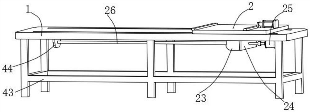
[0036] Such as figure 1 , figure 2 , Image 6 As shown, as a preferred embodiment, on the basis of the above-mentioned method, the sliding mechanism includes a moving groove 22 set horizontally on the upper end surface of the table top 1 and passing through the table top 1, and the lower end surface of the moving plate 2 is vertically fixedly installed with a sliding and penetrating moving groove 22 The moving block 23, the side wall of the moving block 23 is vertically fixedly installed with a power plate 24, and the lower end surface of the table top 1 is horizontally fixedly installed with a first motor 25, and the first motor 25 adopts a servo motor that can be reversible. The positive and negative rotation of the motor 25 indirectly drives the moving plate 2 to move. The output shaft of the first motor 25 is fixedly in...

Embodiment 3

[0038] The schemes in Embodiment 1 and Embodiment 2 are further introduced below in conjunction with specific working methods, see the following description for details:

[0039] Such as figure 1 , Figure 7 , Figure 8 As shown, as a preferred embodiment, on the basis of the above method, the feeding mechanism includes a fixed frame 35 that moves through the side walls on both sides of the table 1, and the fixed frame 35 penetrates the lower end surface of the side wall of the table 1. Lifting plate 36, the lower end surface of table top 1 is fixedly equipped with L-shaped support frame 37, and vertically fixedly installed on the upper end surface of support frame 37 is the lifting electric push rod 38 whose free end is fixedly connected with the lower end surface of lifting plate 36, and the fixed frame 35 moves away from One side of the plate 2 is horizontally provided with a feeding electric push rod 39 fixedly installed on the upper end of the table top 1, and the free ...


PUM


Abstract

The invention relates to a corrugated carton flattening assembly, and belongs to the technical field of corrugated cartons, the corrugated carton flattening assembly comprises a transversely arranged n-shaped table top, a moving plate is transversely mounted on the upper end face of the table top through a sliding mechanism, a fixing mechanism is mounted on the upper end face of the moving plate, and a first fixing frame is fixedly mounted at one end of the outer side wall of the table top; a connecting plate is transversely and fixedly installed on the inner side wall of the first fixing frame through a first electric push rod, the connecting plate is connected with the inner top face of the first fixing frame through a connecting mechanism, a soft brush plate is arranged, the first electric push rod indirectly drives the upper surface of the soft brush plate to conduct cleaning, and paper scrap particles on the upper surface of a paperboard are removed; paper scrap particles are prevented from leaving marks on the surface of the paperboard, so that the flattening quality of the device is improved.

Description

technical field [0001] The invention relates to a corrugated carton flattening component, which belongs to the technical field of corrugated cartons. Background technique [0002] There may be paper dust particles attached to the surface of the cardboard of corrugated boxes during flattening, which will affect the quality of the flattening of the corrugated box cardboard by the device. Flattening, the flattening effect is often not very good, and the existing flattening device generally puts the corrugated cardboard on the device manually, and then removes it after finishing the flattening work, which not only requires labor, but also has a low degree of intelligence , more time-consuming, reducing the working efficiency of the device. [0003] Therefore, we improve this and propose a corrugated box flattening component. Contents of the invention [0004] (1) The technical problem to be solved by the present invention is: the flattening effect is poor, and it needs to ma...

Claims


Application Information

Patent Timeline
Patent Type & Authority Applications(China)
IPC IPC(8): B31B50/59
CPCB31B50/59
Inventor 谌俊
Owner 南京塞拉多科技有限公司
Why Eureka
Try Eureka