
Combined control arm bushing with reinforcing mechanism

A strengthening mechanism and combined technology, which is applied to the cantilever mounted on the pivot, suspension, transportation and packaging, etc., can solve the large force between the body and the bushing of the control arm, and the rubber deformation of the original structural bushing Large size, unqualified durability of control arm bushing, etc., to achieve the effect of enhancing rigidity, increasing service life and reducing service life

Active Publication Date: 2022-03-01
ANHUI ZHONGDING NVH
View PDF4 Cites 0 Cited by
  • Summary
  • Abstract
  • Description
  • Claims
  • Application Information

AI Technical Summary

Problems solved by technology

However, when the car is used in extreme conditions, the force between the body and the bushing of the control arm is too large, and the rubber deformation of the bushing of the original structure is large, resulting in the durability of the bushing of the control arm being unqualified.
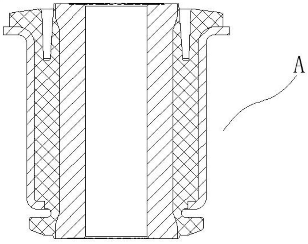
like image 3 As shown, it is a control arm bushing in the prior art. When used in extreme conditions, the force between the body and the control arm bushing is too large, and the rubber deformation of the original structure bushing is large, resulting in the control arm bushing The durability of the set is unqualified

Method used


Image

  • Combined control arm bushing with reinforcing mechanism
  • Combined control arm bushing with reinforcing mechanism
  • Combined control arm bushing with reinforcing mechanism

Examples


Embodiment

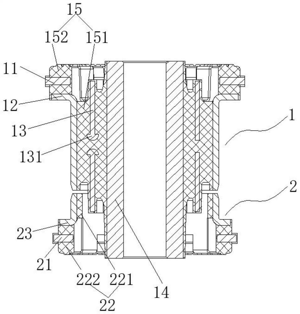
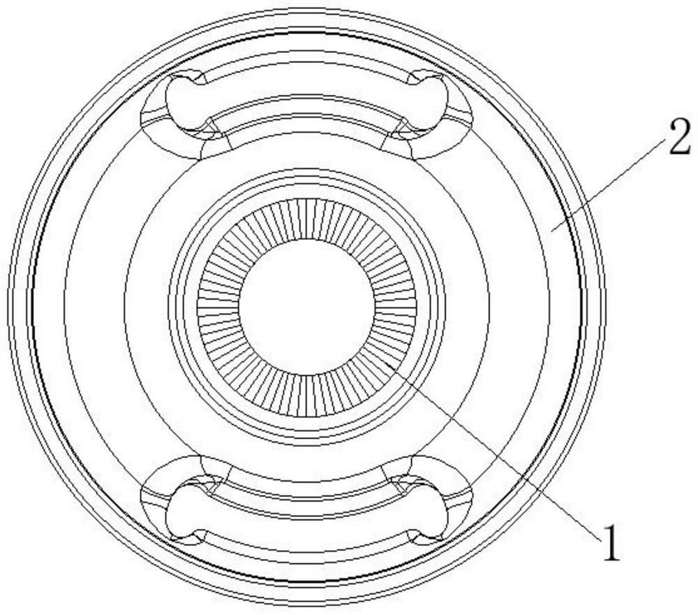
[0023] Such as figure 1 , figure 2 As shown, the combined control arm bushing with reinforcing mechanism includes a first component 1 and a second component 2, and the first component 1 is assembled with the second component 2;

[0024] The first assembly 1 includes: a first outer casing 12, a first rubber layer 15, and an inner sleeve 14 disposed from the outer to the inner, and the first outer casing 12, the first rubber layer 15, and the inner sleeve 14 are provided as a cylindrical shape. The first rubber layer 15 includes a first long side 151 and a first short side 152, the first long side 151 and the first short side 152, which is set, and the first long side 151 The outer wall of the sleeve 142 is disposed at the first long side 151 away from the second component 2; the first short side 152 is provided with a first reinforcing gasket 11 for enhancing the first short side 152. The rigidity at the time of axial force; a medium sleeve 13 is provided in the first long side 151...


PUM


Abstract

The invention provides a combined control arm bushing with a reinforcing mechanism, which comprises a first assembly and a second assembly, and the first assembly and the second assembly are assembled for use; the first assembly comprises a first outer sleeve, a first rubber layer and an inner sleeve which are sequentially arranged from outside to inside, the first outer sleeve, the first rubber layer and the inner sleeve are cylindrical, the first rubber layer comprises a first long edge and a first short edge, the first long edge and the first short edge are arranged in an L shape, the first long edge is arranged on the outer wall of the inner sleeve in a sleeving mode, and the first short edge is arranged on the outer wall of the inner sleeve in a sleeving mode; the first short edge is arranged at one end, far away from the second assembly, of the first long edge; a first reinforcing gasket is arranged in the first short edge; a middle sleeve is arranged in the first long edge; the second assembly comprises a second outer sleeve and a second rubber layer which are sequentially arranged from outside to inside, the second rubber layer comprises a second long edge and a second short edge, the second long edge and the second short edge are arranged in an L shape, and a second reinforcing gasket is arranged in the second short edge.

Description

Technical field [0001] The present invention relates to the field of automotive control arm bushing, and more particularly to a combined control arm bushing with reinforcing mechanisms. Background technique [0002] The control arm bushing is an important part of the wheel and the body connection. The structure is more complicated, superior to shock absorption performance, significantly improve the smoothness of the vehicle, effectively alleviate the force of the control arm, improve the comfort and control of the ride Life. However, when the vehicle is used in the extreme conditions, the stress between the body and the control arm bushing is too large, and the original structural bushing rubber deformation is large, resulting in a long time to do not qualify the control arm bush. Such as image 3 As shown, it is a control arm bushing in the prior art, and when the limit conditions are used, the force between the body and the control arm bushing is too large, the original structur...

Claims


Application Information

Patent Timeline
Patent Type & Authority Applications(China)
IPC IPC(8): B60G7/04
CPCB60G7/04Y02E30/30
Inventor 何仕生程春明
Owner ANHUI ZHONGDING NVH
Learn More