Electromagnetic flow measuring and adjusting instrument

An electromagnetic flow, measuring and adjusting instrument technology, applied in the field of measuring and adjusting instruments, can solve the problems of reduced work efficiency, slow disassembly and assembly, cumbersome cable heads, etc., and achieves the effect of fast fixing and convenient disassembly

Pending Publication Date: 2022-03-01
大庆科力远石油装备制造有限公司
View PDF0 Cites 0 Cited by
  • Summary
  • Abstract
  • Description
  • Claims
  • Application Information

AI Technical Summary

Problems solved by technology

[0005] In order to make up for the shortcomings of the existing technology, the cable head on the tester needs to be replaced frequently when it is used for a long time. The traditional method of replacing the ca

Method used


Image

  • Electromagnetic flow measuring and adjusting instrument
  • Electromagnetic flow measuring and adjusting instrument
  • Electromagnetic flow measuring and adjusting instrument

Examples


Example Embodiment

[0027] Example one

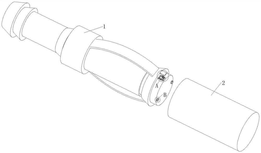
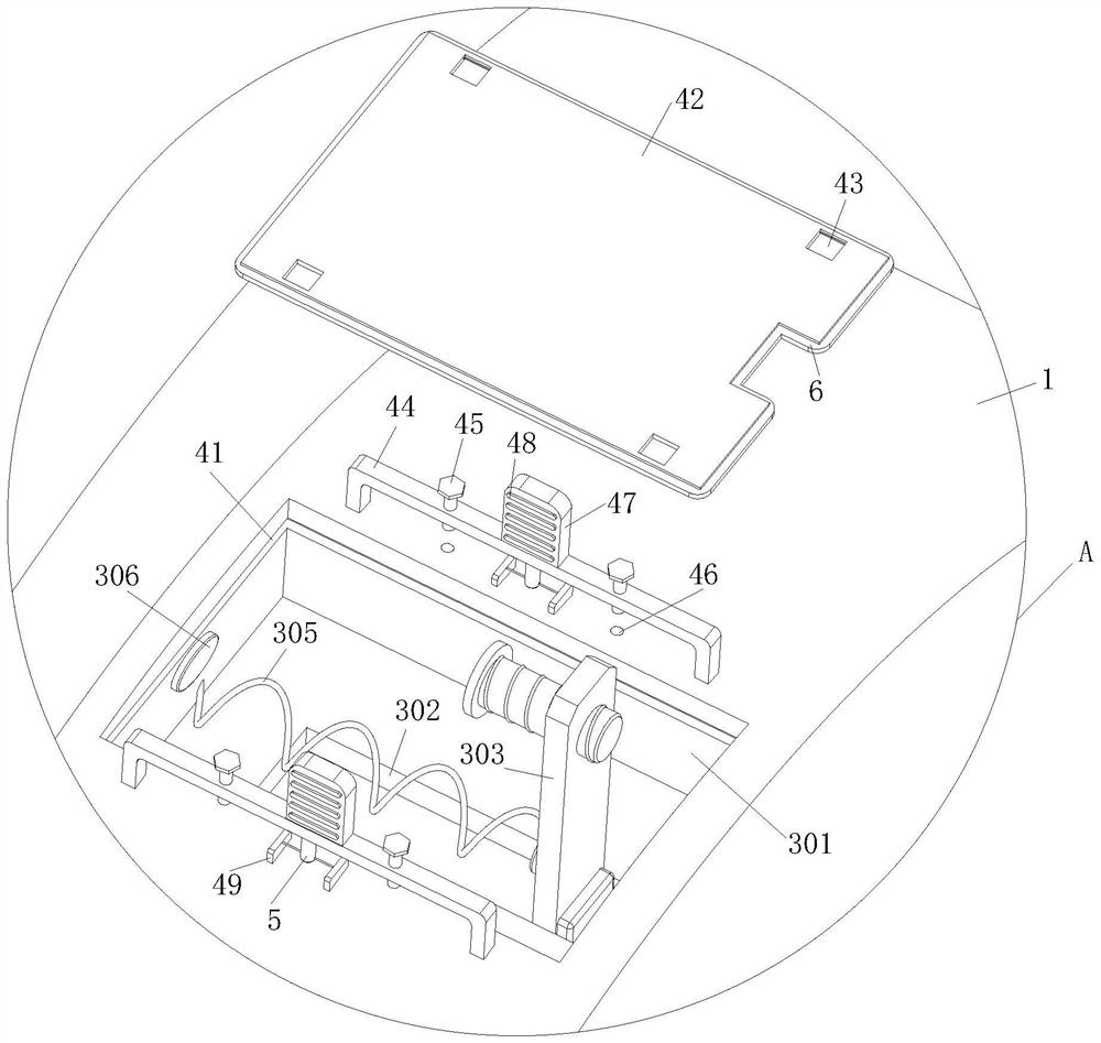
[0028] See Figure 1-6 As shown, the electromagnetic flow measurement includes a cable head 1, an electric current collecting control 2; an electric current collecting control 2 is provided on one side of the cable head 1, and two placed grooves 301 are opened on the surface of the cable head 1. , Two of the placed grooves 301 are symmetrically distributed in the central axis of the cable head 1, and the inner portion of the placement groove 301 is opened, and the inner sliding connection of the chute 302 has a sliding block 303, and the slider block 303 One side thread is connected to a first bolt 304, and one side of the placing groove 301 is fixedly mounted having a spring 305, and the other end of the spring 305 is fixedly mounted, and the one end of the electric current collecting control 2 is opened. When the first threaded hole 309 operates, the first thread 304 on the sliding block 303 and the first thread control 2 on the first threaded hole 309 on the...

Example Embodiment

[0036] Example 2

[0037] See Figure 7 As shown, Comparative Examples 1, as another embodiment of the present invention, two round slots 7 have two round slots 7, and the two of the circle grooves 7 are distributed in a central axis symmetry distribution of the cable head 1; When working, when the cable head 1 is needed, by placing the hand into the round groove 7 of the cable head 1, it is convenient to pick up the cable head 1 by the round groove 7, and the round slot 7 increases friction. The role makes it to prevent slip when picking up the cable head 1.

[0038] Working principle, in front of the cable head 1, the sliding block 303 slides in the direction of the magnet positive electrode 306, and the sliding block 303 is moved together with the magnet negative electrode 307 such that the magnet positive electrode 307 and the magnet positive electrode 306 are attached to each other, and then the sliding block 303 Fixed, convenient for the mounting of the sliding block 303, bef...


PUM


Abstract

The invention belongs to the field of measuring and adjusting instruments, and particularly relates to an electromagnetic flow measuring and adjusting instrument which comprises a cable head and an electric current collecting control. One side of the cable head is provided with an electric current collection control, the surface of the cable head is provided with two placement grooves, the two placement grooves are symmetrically distributed about the central axis of the cable head, the placement grooves are internally provided with sliding grooves, the interiors of the sliding grooves are slidably connected with sliding blocks, and one sides of the sliding blocks are in threaded connection with first bolts. A spring is fixedly mounted on one side of the placement groove; the spring drives the sliding block and the first bolt to slide in the direction of the electric current collecting control, one end of the first bolt enters the first threaded hole, at the moment, the first bolt on the sliding block is screwed, the first bolt and the first threaded hole in the electric current collecting control are fixed, and then the cable head and the electric current collecting control are mutually fixed. Therefore, the purpose of quickly fixing the cable head and the electric current collection control is achieved, and the purpose of convenient disassembly is achieved.

Description

Technical field [0001] The present invention relates to the field of tuning, and is specifically a electromagnetic flow rate modulator. Background technique [0002] The tuning is a test and regulatory instrument. [0003] The test instrument is used in the tubing, controlling the downhilation flow rate, test and adjustment through computer and floor box, test and adjustment, and the test and adjustment process, the collecting cubes are opened in the tubing, and the injection medium completely enters the electromagnetic flowmeter. The internal flow is measured, downhole flow, pressure, temperature and other parameters directly read. [0004] When the cable head on the test is often replaced frequently, and the traditional replacement cable head is too cumbersome, and it is slow to disassemble, which greatly reduces work efficiency; therefore, for the above problem, electromagnetic flow test Conditioning. Inventive content [0005] In order to make up for the shortcomings of the ...

Claims


Application Information

Patent Timeline
IPC IPC(8): E21B43/12E21B47/00E21B17/02H02G15/06
CPCE21B43/12E21B47/00E21B17/023H02G15/06
Inventor 刘晓志马彦荣
Owner 大庆科力远石油装备制造有限公司
Why Eureka
Try Eureka