Railway vehicle speed simulation experiment device and working condition simulation method

A rail vehicle and experimental device technology, applied in the field of sensor system detection of rail vehicles, to achieve the effect of easy portability, strong integrity, and accurate testing

Pending Publication Date: 2022-03-01
成都长客新筑轨道交通装备有限公司
View PDF0 Cites 0 Cited by
  • Summary
  • Abstract
  • Description
  • Claims
  • Application Information

AI Technical Summary

Problems solved by technology

[0005] In order to solve the problem of simulating rail vehicles at different speeds and directions of travel and simulating working conditions during operation, this scheme provides a rail vehicle speed simulation experiment device and a working condition simulation method

Method used


Image

  • Railway vehicle speed simulation experiment device and working condition simulation method
  • Railway vehicle speed simulation experiment device and working condition simulation method
  • Railway vehicle speed simulation experiment device and working condition simulation method

Examples


Embodiment 1

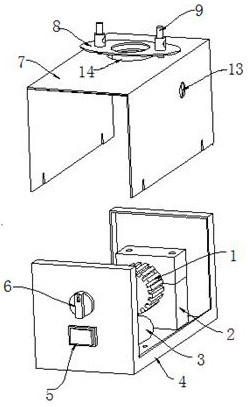
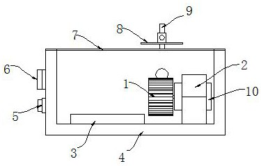
[0045] Such as Figure 1 to Figure 7 As shown, in this embodiment, a rail vehicle speed simulation experiment device is designed, including a power supply, a pseudo-speed runner 1, a pseudo-speed motor 10, a base 4, a cover, and a driving circuit.

[0046] Wherein, the pseudo-speed runner 1 is driven by the pseudo-speed motor 10, and the speed is detected by a speed sensor on the rail vehicle.

[0047] The base 4 is provided with a motor mounting base 2, the pseudo-speed motor 10 is fixed on the motor mounting base 2, and the base 4 is U-shaped. The power supply is electrically connected to the pseudo-speed motor 10 through the driving circuit; the power supply adopts the battery 3 and is installed on the inner bottom of the base 4 .

[0048] The drive circuit includes a speed control knob 6 and a switch 5, the switch 5 and the speed control knob 6 are installed on the side wall of the base 4; the changeover switch 5 is used to switch the rotation direction of the pseudo-spee...

Embodiment 2

[0054] Use the rail vehicle speed simulation experimental device in embodiment 1 to simulate the experimental method of wheel skid condition: comprise the following steps:

[0055] S11: matching and connecting a plurality of speed sensors to one of the speed simulation experiment devices; the plurality of speed sensors are respectively used to detect wheel axle speeds at different positions;

[0056] S12: Operate the rail vehicle so that it is in rapid braking detection and release the parking brake;

[0057] S13: Operate the switching switch 5 of the speed simulation experiment device, so that the steering and rotation speed of each pseudo-speed runner 1 are the same, and the rotation speed reaches the set value;

[0058] S14: Adjust the speed control knob 6 of any speed simulation experiment device to decrease the speed of the corresponding pseudo-speed wheel 1 .

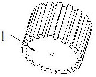
[0059] The pseudo-speed runner 1 is a gear, and gear teeth are evenly distributed around the gear; in the step...

Embodiment 3

[0062] Use the rail vehicle speed simulation experimental device in embodiment 1 to simulate the experimental method of wheel abnormal wear condition: comprise the following steps:

[0063] S21: matching and connecting a plurality of speed sensors to one of the speed simulation experiment devices; the plurality of speed sensors are respectively used to detect wheel axle speeds at different positions;

[0064] S22: Replace the quasi-speed runner 1 in any speed simulation experiment device with a missing gear; the missing gear is provided with a missing tooth position 11 in the circumferential direction;

[0065] S23: Operate the rail vehicle so that it is in a coasting state and release the parking brake;

[0066] S24: Operate the switching switch 5 of the speed simulation experiment device, so that the steering and rotation speed of each pseudo-speed runner 1 are the same, and the rotation speed reaches the set value.

[0067] Optional: in the step S24, if the speed detection...


PUM


Abstract

The invention belongs to the technical field of sensor system detection of railway vehicles, and particularly relates to a railway vehicle speed simulation experiment device and a working condition simulation method, and the device comprises a power supply, a quasi-speed rotating wheel, a quasi-speed motor and a drive circuit. The quasi-speed rotating wheel is driven by the quasi-speed motor, and the speed is detected by a speed sensor on the railway vehicle; the power supply is electrically connected with the quasi-speed motor through the driving circuit; the driving circuit comprises a speed regulation knob and a change-over switch; the change-over switch is used for switching the rotation direction of the pseudo-speed motor; and the speed adjusting knob is used for adjusting the rotating speed of the quasi-speed motor. Different vehicle speeds and different advancing directions of the rail vehicle in the advancing process can be simulated, so that the safety and reliability of circuits such as a corresponding sensor system and a feedback control system including a brake system or an alarm system in the rail vehicle can be tested.

Description

technical field [0001] The invention belongs to the technical field of rail vehicle sensor system detection, and in particular relates to a rail vehicle speed simulation experiment device and a working condition simulation method. Background technique [0002] The traction control, braking force control, vehicle emergency braking, vehicle speed limit and door zero-speed protection function of rail vehicles and the judgment of special working conditions of the vehicle all need to be determined in combination with the vehicle speed. Speed ​​acquisition is the safety of the whole vehicle. One of the key factors of protection control, so it is particularly important to test the function of the speed sensor and the protection function under the special working conditions of the vehicle during the production and debugging of the vehicle. [0003] Metro vehicles generally use Hall-type sensors. Hall-type sensors can collect vehicle speed through non-contact measurement. When the ve...

Claims


Application Information

Patent Timeline
Patent Type & Authority Applications(China)
IPC IPC(8): G01M17/007
CPCG01M17/007
Inventor 唐远志易森杜宇捷燕伟康唐华波王罗向秦
Owner 成都长客新筑轨道交通装备有限公司
Why Eureka
Try Eureka