Connector capable of self-locking

A connector and self-locking technology, applied in the direction of connection, parts of the connection device, fixed/insulated contact components, etc., can solve the problems of inconvenient replacement, replacement loss, and expensive overall equipment value

Pending Publication Date: 2022-03-01
CHINA AVIATION OPTICAL-ELECTRICAL TECH CO LTD
View PDF0 Cites 0 Cited by
  • Summary
  • Abstract
  • Description
  • Claims
  • Application Information

AI Technical Summary

Problems solved by technology

After the connector is locked, it is plugged and pulled out under live conditions. Due to the existence of arc, it will cause damage to the device port contact or the connector contact.
In the process of plugging and unplugging, if the connector

Method used


Image

  • Connector capable of self-locking
  • Connector capable of self-locking
  • Connector capable of self-locking

Examples


Example Embodiment

[0034]Next, the technical solutions in the embodiments of the present invention will be described in connection with the drawings of the embodiments of the present invention, and it is understood that the described embodiments are merely the embodiments of the present invention, not all of the embodiments. Based on the embodiments of the present invention, all other embodiments obtained by those of ordinary skill in the art are in the range of the present invention without making creative labor premise.

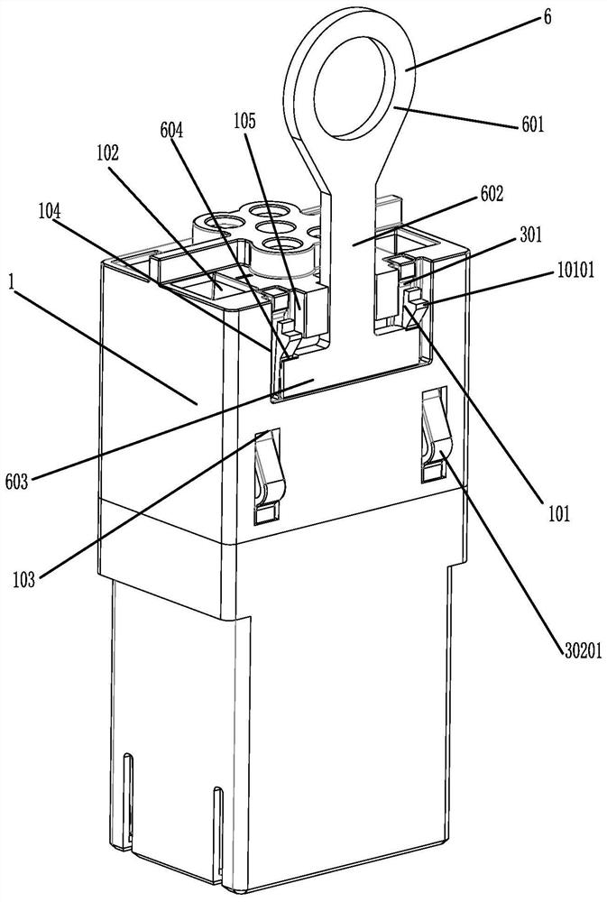
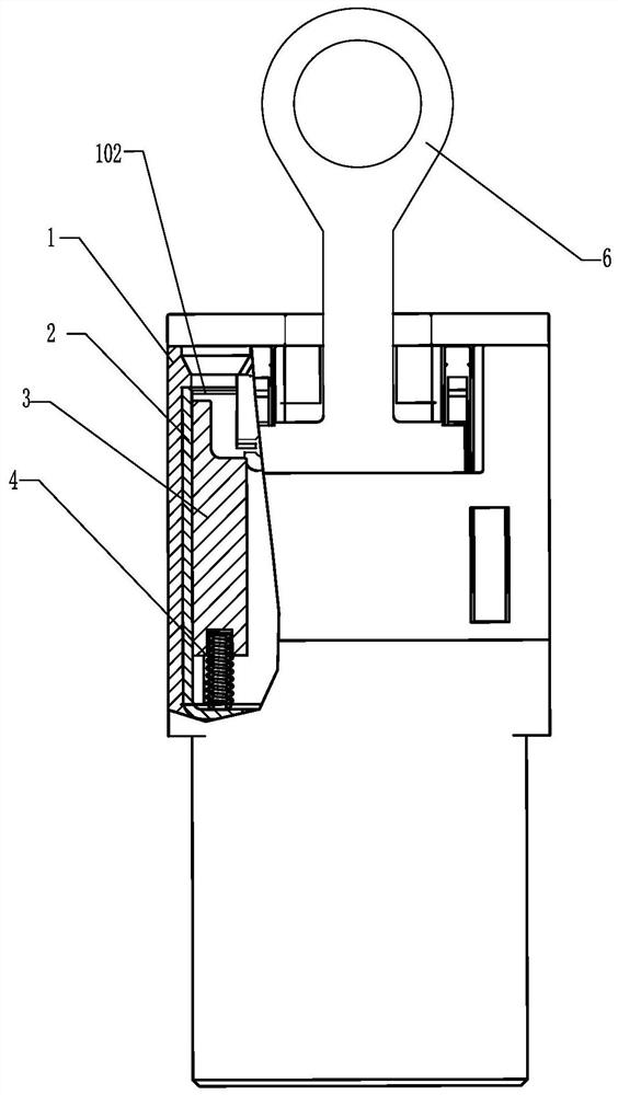
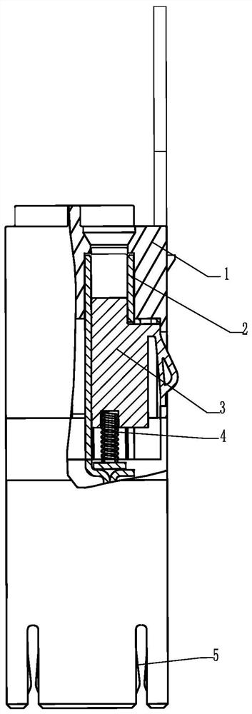
[0035] An embodiment of a self-locking connector, such as Figure 1 to 5 As shown, the connector includes a housing 1, a slider 3, a spring 4. One end of the housing 1 is a pair of interpolation, for inserting the port of the mounting panel on the device, the other end is a terminal, for connecting the wire, the end of the wire is a wire terminal, the wire terminal is inserted into the connector. The insertion direction of the wire terminal is the same as the connector.

[0036] A...


PUM


Abstract

A connector capable of being self-locked comprises a shell, at least two terminals are arranged in the shell, a sliding block and an elastic piece are arranged at the position, corresponding to any terminal, in the shell, and the sliding block abuts against the interior of the shell under the elastic force effect of the elastic piece and blocks a wiring port, used for being connected with a wire terminal in an inserted mode, in the shell. The elastic protrusions are arranged on the sliding blocks, and when the connector is inserted, the elastic protrusions are extruded and contracted, so that the sliding blocks are released from the clamping state. When the connector is not inserted into equipment, the lead terminal cannot be inserted into the connector, so that the connector is prevented from being inserted into the equipment in a live-line manner; if the wire terminals are not removed, the connector cannot be pulled out from the equipment, so that electric arcs are prevented from being generated during pulling out; therefore, hot plugging of the connector can be avoided, electric arcs are prevented from being generated in the plugging process of the connector, and damage of the electric arcs to equipment and the connector is avoided. The connector fundamentally avoids the generation of the electric arc instead of the conventional weakening of the electric arc, and can be applied to wider occasions.

Description

technical field [0001] The invention relates to a connector, in particular to a self-locking connector. Background technique [0002] At present, the commonly used method of plugging and unplugging the connector and the device port is that the connector is first locked and then plugged into the device port. After the connector is locked and plugged in under live conditions, due to the existence of the arc, it will cause damage to the device port contact or the connector contact. In the process of plugging and unplugging, if the connector contact is damaged due to arc burning, you can consider replacing it with a new connector. However, if the device port contact is burnt, it is often inconvenient to replace, and the overall equipment value is more expensive. cause greater losses. Therefore, there is a need for a self-locking connector, which can be inserted into the port of the equipment cabinet when there is no locking wire, that is, the connector is in an open circuit st...

Claims


Application Information

Patent Timeline
IPC IPC(8): H01R13/53H01R13/40H01R13/639
CPCH01R13/53H01R13/40H01R13/639
Inventor 郝清坡王禄芳刘毅李桥飞李敬
Owner CHINA AVIATION OPTICAL-ELECTRICAL TECH CO LTD
Why Eureka
Try Eureka