
External force toppling prevention type self-pressure-relief power distribution cabinet

A power distribution cabinet and self-relieving technology, which is applied to the substation/power distribution device housing, electrical components, switchgear, etc., can solve the problems of internal component position deviation, easy to dump, and insufficient quality, and achieve The effect of avoiding positional deviation and enhancing stability

Pending Publication Date: 2022-03-01
王徐
View PDF1 Cites 1 Cited by
  • Summary
  • Abstract
  • Description
  • Claims
  • Application Information

AI Technical Summary

Problems solved by technology

[0006] The purpose of the present invention is to provide an anti-external force dumping type self-relieving pressure distribution cabinet to solve the problem that when affected by external force in the above-mentioned background technology, the phenomenon of dumping easily occurs due to its insufficient quality, resulting in the protection of the overall device. The performance cannot be guaranteed. At the same time, when the existing power distribution cabinet is hit by external force, it cannot quickly locate the electrical components inside the device in time, which leads to the problem that the position of the internal components is prone to shift.

Method used


Image

  • External force toppling prevention type self-pressure-relief power distribution cabinet
  • External force toppling prevention type self-pressure-relief power distribution cabinet
  • External force toppling prevention type self-pressure-relief power distribution cabinet

Examples


Embodiment Construction

[0033] The following will clearly and completely describe the technical solutions in the embodiments of the present invention with reference to the accompanying drawings in the embodiments of the present invention. Obviously, the described embodiments are only some, not all, embodiments of the present invention. Based on the embodiments of the present invention, all other embodiments obtained by persons of ordinary skill in the art without making creative efforts belong to the protection scope of the present invention.

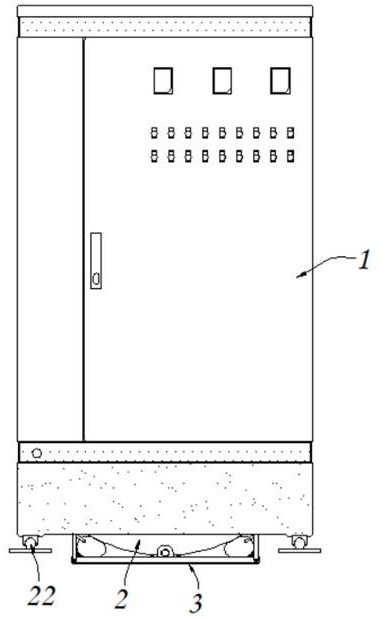
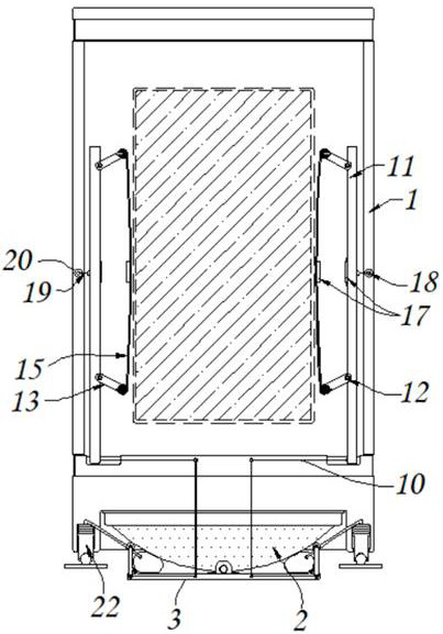
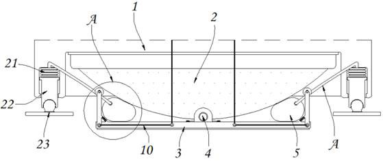
[0034] see Figure 1-7 , the present invention provides a technical solution: an anti-external force dumping self-relieving power distribution cabinet, including a power distribution cabinet body 1, a counterweight 2, a support seat 3, a connecting shaft 4, an adhesive airbag 5, and movable parts 6. Return spring 7, docking hose 8, adhesive layer 9, first traction rope 10, connecting piece 11, first torsion spring 12, conflicting piece 13, winding roller 14, p...


PUM


Abstract

The invention discloses an external force toppling prevention type self-pressure-relief power distribution cabinet which comprises a power distribution cabinet body, the lower end of the power distribution cabinet body is fixedly connected with a balancing weight, the lower end of the balancing weight is in butt joint with a supporting seat, a connecting shaft is installed at the upper end of the supporting seat in a penetrating mode, and meanwhile the connecting shaft is connected with the inner side of the balancing weight; the bonding air bag is connected to the balancing weight in a bonding mode and connected with the upper end of the supporting base, a butt joint hose is installed at the outer end of the bonding air bag in a penetrating mode, and a bonding layer is connected to the inner side of the edge end of the butt joint hose in a bonding mode; and the connecting piece is embedded in the inner end of the power distribution cabinet body. According to the external force toppling prevention type self-pressure-relief power distribution cabinet, in the process that the device is subjected to external force, the device stably performs angle movement through the balance weight piece with the spherical structure at the lower end in advance, so that the contacted external force is subjected to force relief treatment, the device forms a tumbler-shaped supporting structure, and the undesirable phenomena such as toppling and the like of the device are avoided.

Description

technical field [0001] The invention relates to the technical field of power distribution cabinets, in particular to a self-relieving power distribution cabinet that prevents external force from toppling over. Background technique [0002] The power distribution cabinet is a device suitable for switching on and protecting components in various workplaces, and has a wide range of applications; [0003] For example, a high and low voltage power distribution cabinet with a publication number of CN211908144U has a sensor-ventilated power distribution cabinet, and the protective restraint device is sleeved in the wire hole, so that when the wire is inserted into the power distribution cabinet, it is reduced by the protective sponge. The friction will not cause wear and tear, and then the multiple wires are fixed and restrained by the fixing hoop to facilitate maintenance; [0004] However, when the existing power distribution cabinets are affected by external forces, due to thei...

Claims


Application Information

Patent Timeline
Patent Type & Authority Applications(China)
IPC IPC(8): H02B1/56H02B1/54H02B1/50H02B1/30H02B1/32H02B1/04H02B13/025
CPCH02B1/565H02B1/54H02B1/50H02B1/306H02B1/303H02B1/32H02B1/04H02B13/025
Inventor 王徐
Owner 王徐
Learn More