
Circuit board connecting mechanism

A connection mechanism and circuit board technology, which is applied in the direction of printed circuits, printed circuits connected with non-printed electrical components, electrical components, etc., can solve the problems of small screw size, operator trouble, slow assembly speed, etc., and achieve assembly efficiency High, easy to operate, quick replacement effect

Pending Publication Date: 2022-03-01
李达
View PDF0 Cites 0 Cited by
  • Summary
  • Abstract
  • Description
  • Claims
  • Application Information

AI Technical Summary

Problems solved by technology

[0003] The above assembly methods need to be locked by screws. Whether it is installation or removal, the screws need to be disassembled. The operation is more cumbersome, the assembly speed is slow, the efficiency is low, and the screws are small, and the screws are prone to loss during the assembly process. Stable, causing greater distress to the operator

Method used


Image

  • Circuit board connecting mechanism
  • Circuit board connecting mechanism
  • Circuit board connecting mechanism

Examples


Embodiment Construction

[0029] The present invention will be further described below in conjunction with specific embodiments and accompanying drawings.

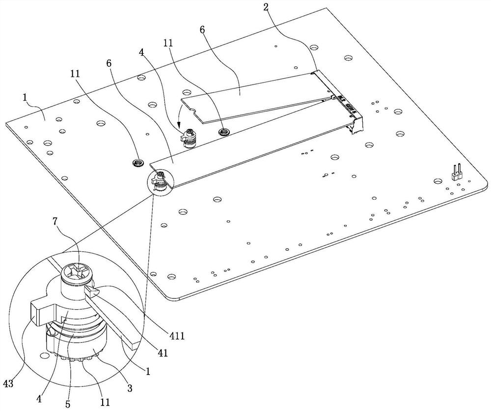
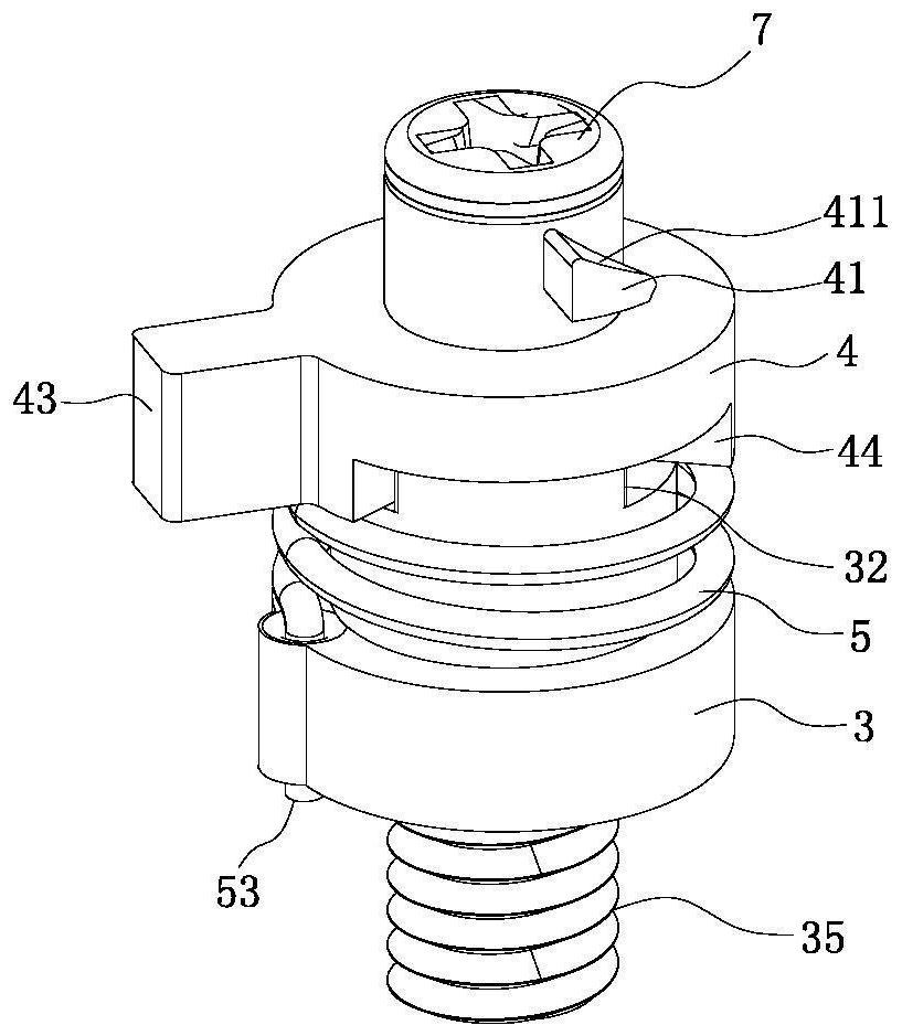
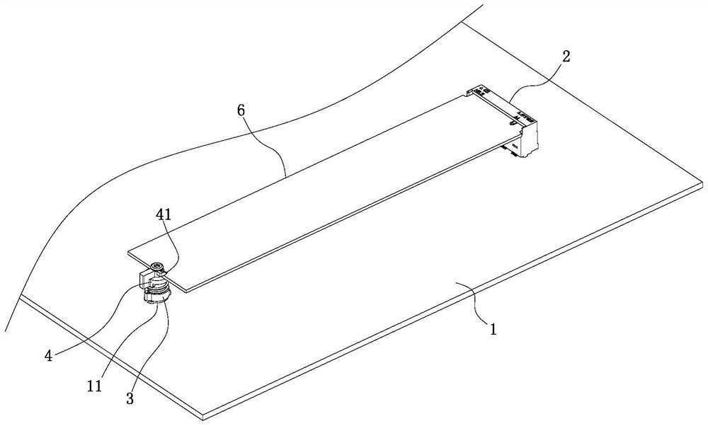
[0030] See Figure 1-9 Shown is a circuit board connection mechanism, which includes a circuit board 1 , a connector 2 , a fixing member 3 , a rotary buckle 4 and an elastic element 5 .

[0031] The connector 2 is fixed on the circuit board 1 and is used for plugging the electronic device 6 and forming an electrical connection so that data can be transmitted stably. In this embodiment, the electronic device 6 is an M.2 solid state drive. The M.2 solid-state drive is a solid-state drive with an M.2 interface. It is widely used on circuit boards due to its small size and high-speed transmission performance. For example, most computers currently use M. 2 SSDs.

[0032] The fixing part 3 is fixed on the circuit board 1 and can be disassembled relative to the circuit board 1; the rotating buckle 4 is mounted on the upper end of the fixing part 3 in a...


PUM


Abstract

The invention discloses a circuit board connecting mechanism, which comprises a connector fixed on a circuit board, a fixed part, a rotary buckle rotatably mounted at the upper end of the fixed part, and an elastic element arranged between the fixed part and the rotary buckle, and the rotary buckle can be reset through the elastic element after rotating relative to the fixed part; a buckle body is arranged on the outer side of the upper end of the rotary buckle; one end of the electronic device is connected with the connector, the other end of the electronic device is pressed down, the other end of the electronic device is driven to press the guide inclined face of the buckle body, and the rotary buckle is forced to rotate relative to the fixing piece and compress the elastic element. The buckle body is pressed on the upper end face of the other end of the electronic device to lock the other end of the electronic device. According to the invention, after the other end of the electronic device is directly pressed down, the other end of the electronic device can be locked on the circuit board, the operation is simple and convenient, rapid replacement can be realized, and the assembly efficiency is extremely high.

Description

Technical field: [0001] The invention relates to the field of electronic technology, in particular to a circuit board connection mechanism. Background technique: [0002] When an electronic device (such as an M.2 solid-state drive) is connected to a circuit board, it is necessary to insert one end of the electronic device into the connector on the circuit board to form electrical continuity, and place the other end of the electronic device on the circuit board. on the positioning column set on the board, and screw through the holes of the circuit board to fix the positioning column on the positioning column, so as to fasten the other end of the electronic device to the circuit board, and finally the entire electronic device is stably assembled on the circuit board board, and ensure that the electronic device and the circuit board form a stable electrical connection. [0003] The above assembly methods need to be locked by screws. Whether it is installation or removal, the s...

Claims


Application Information

Patent Timeline
IPC IPC(8): H05K1/18
CPCH05K1/181
Inventor 李娜
Owner 李达
Learn More