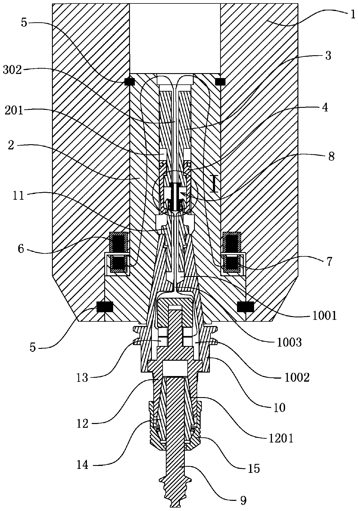
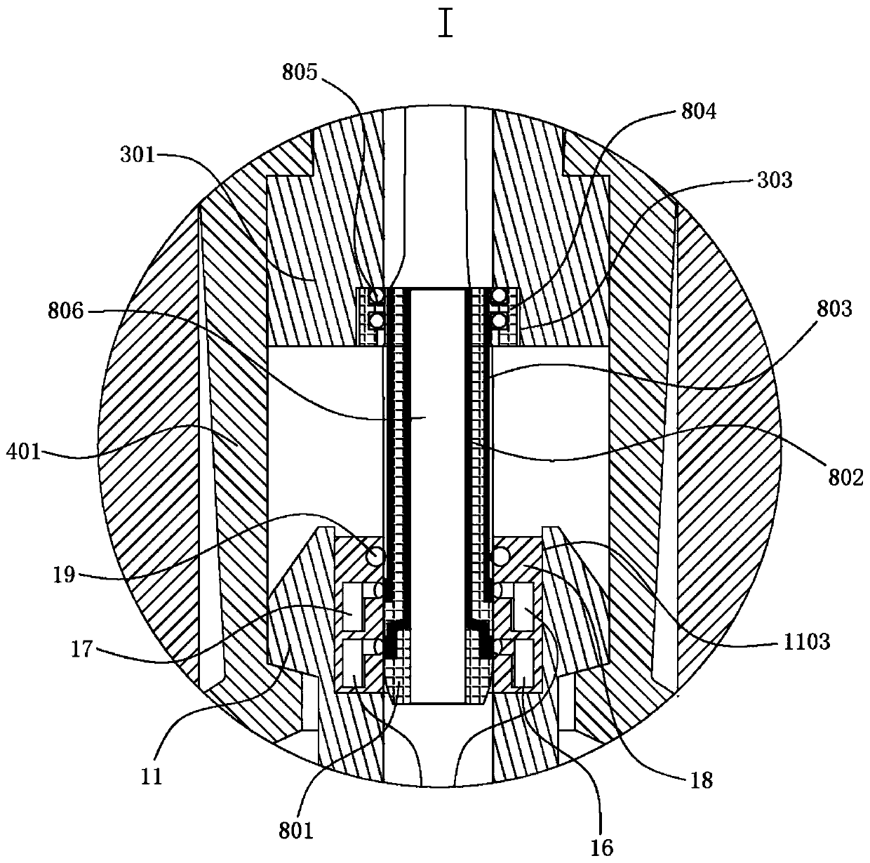
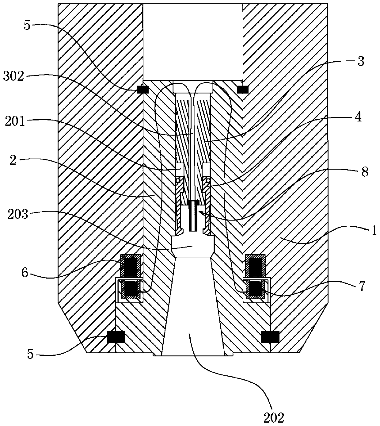
Electric connection structure of ultrasonic main shaft

An electrical connection structure, ultrasonic technology, applied in the direction of connection, two-part connection device, parts of the connection device, etc., can solve problems such as damage to the power plug or power connector, damage to the second electrode or second conductive element, etc., to eliminate The effect of safety hazards, reducing the difficulty of alignment, and avoiding leakage

Pending Publication Date: 2019-11-19
CONPROFE TECH GRP CO LTD +1
View PDF0 Cites 0 Cited by
  • Summary
  • Abstract
  • Description
  • Claims
  • Application Information

AI Technical Summary

Problems solved by technology

[0005] 1. When the insertion part of the ultrasonic tool holder has not been fully inserted into the sleeve and positioned in the sleeve hole of the rotating shaft, since the ultrasonic tool holder still has a positional deviation from the rotating shaft, relatively, the power plug of the ultrasonic tool holder The first and second electrodes and the first and second conductive elements of the power connector have not yet been accurately aligned. Therefore, when the first and second electrodes of the power plug are first inserted into the first and second conductive elements of the power connector, it is easy to cause Damage to the power plug or power connector
[0006] 2. Since the shapes of the second conductive element of the power connector and the second electrode of the power plug are quite tapered, during the insertion process of the second electrode of the power plug and the second conductive element of the power connector, The two must be aligned more precisely. If the position is slightly deviated, the second electrode or the second conductive element is easily damaged due to abrasion or bending

Method used


Image

  • Electric connection structure of ultrasonic main shaft
  • Electric connection structure of ultrasonic main shaft
  • Electric connection structure of ultrasonic main shaft

Examples


Embodiment Construction

[0039] The following will clearly and completely describe the technical solutions in the embodiments of the present invention with reference to the accompanying drawings in the embodiments of the present invention. Obviously, the described embodiments are only some, not all, embodiments of the present invention. Based on the embodiments of the present invention, all other embodiments obtained by persons of ordinary skill in the art without creative efforts fall within the protection scope of the present invention.

[0040] It should be pointed out that in the description of the present invention, the orientation or positional relationship indicated by the terms "upper", "lower", "left", "right", "top", "bottom" etc. are based on those shown in the accompanying drawings Orientation or positional relationship is only for the convenience of describing the present invention and simplifying the description, and does not indicate or imply that the referred device or element must have...


PUM


Abstract

The invention relates to the ultrasonic processing technology field and discloses an electric connection structure of an ultrasonic main shaft. Two conductive components are concentrated in a rod bodyat a front end of a pull rod and two conductors are concentrated at a rear end of a pop rivet so that a contact electrical connection portion of an ultrasonic knife handle and a rotating shaft is located in the ultrasonic knife handle or the rotating shaft, and is not exposed in a gap between the ultrasonic knife handle and the rotating shaft. Therefore, an electric leakage phenomenon can be avoided and a potential safety hazard is eliminated. At the same time, the two conductive components are concentrated in the same rod body so that double counterpoint is converted into single counterpoint, which greatly reduces counterpoint difficulty. During a sleeve joint process of the ultrasonic knife handle and the rotating shaft, the rod body and the pop rivet only need to be connected and the conductive components and the conductors can form effective electric connection. And then, stable electrical conduction can be formed between the ultrasonic knife handle and the rotating shaft, and poor contact is not generated.

Description

technical field [0001] The invention relates to the technical field of ultrasonic processing, in particular to an electrical connection structure of an ultrasonic spindle. Background technique [0002] Introducing a high-frequency vibration machining mechanism in the process of machining operations can not only improve the surface roughness of the cutting surface and improve machining accuracy, but also reduce cutting resistance and increase the life of the tool, so it is gradually widely used. [0003] The existing ultrasonic spindle is usually composed of a base body, a rotating shaft and an ultrasonic knife handle. The rotating shaft is erected in the base body, and a sleeve hole is provided at the lower end. A power connector is provided in the sleeve hole. The power connector is provided in a thick tubular shape. The first conductive element, and the second conductive element in the shape of a thin tube is insulated in the first conductive element. The ultrasonic tool ...

Claims


Application Information

Patent Timeline
Patent Type & Authority Applications(China)
IPC IPC(8): H01R13/02H01R13/24H01R13/502H01R13/52H01R24/00B06B1/02B23B19/02
CPCB06B1/02B23Q1/70H01R13/02H01R13/2421H01R13/502H01R13/521H01R24/00
Inventor 颜炳姜李伟秋
Owner CONPROFE TECH GRP CO LTD
Why Eureka
Try Eureka