Application method of PC component multi-form hoisting device

A hoisting device and multi-form technology, applied in the field of PC component multi-form hoisting devices, can solve the problems of destroying the use function of PC components, uneven lifting force, low construction efficiency, etc., and achieve simplified adjustment and leveling work, and even lifting force. , the effect of improving work efficiency

Pending Publication Date: 2022-03-04
CHINA THIRD METALLURGICAL GRP
View PDF6 Cites 0 Cited by
  • Summary
  • Abstract
  • Description
  • Claims
  • Application Information

AI Technical Summary

Problems solved by technology

[0002] The installation of PC components in general construction projects mostly adopts simple single-style installation devices or the most primitive sling sling and simple conventional hoisting methods. In addition, the lifting force is uneven during the hoisting process, and the poor hoisting angle can easily lead to component cracks and damage the use function of the PC component. After the simple lifting method, the PC component is in place, the adjustment and leveling process is more cumbersome, and the professional technical requirements are relatively high. High, difficult construction, heavy workload of construction personnel, low construction efficiency and many other adverse effects

Method used


Image

  • Application method of PC component multi-form hoisting device
  • Application method of PC component multi-form hoisting device

Examples


Embodiment Construction

[0023] The specific embodiments of the present invention will be further described below with reference to the accompanying drawings:

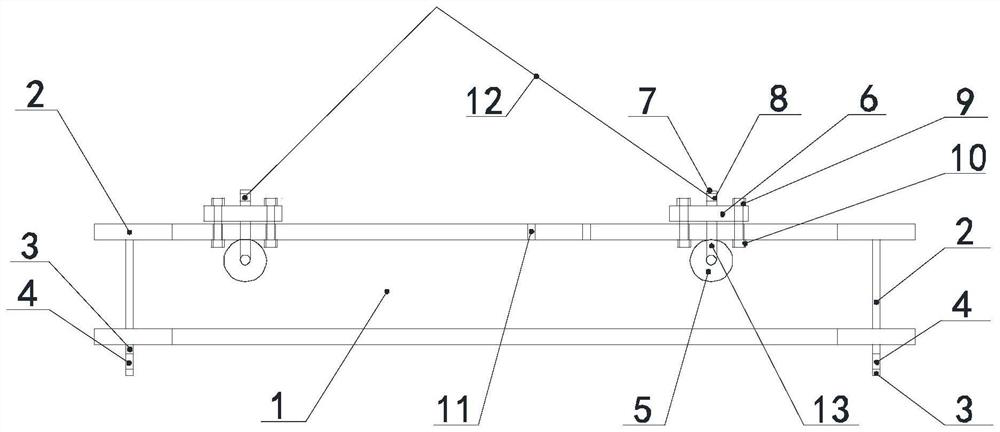
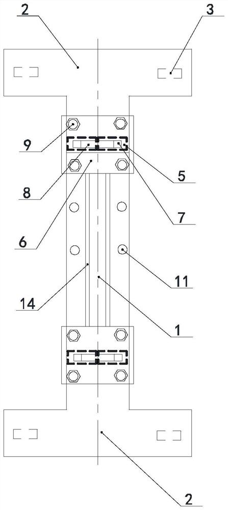
[0024] Such as figure 1 , 2 As shown, a PC member multi-form hoisting device and the method thereof include a tail beam 1, a tail-beam 2, a lifting tuning, a holes 4, a tail pulley 5, a hanging disk 6, lifting The lifting ear 7, the lifting hole 8, the fixing bolt 9, the fixing nut 10, the hanging rails, the centrifugal hole 11, the tail beam 1 side welding tail is tile beam 2, the lower end of the tail beam 2 is separately machined separately two hoisting The central position of the hanging ear 3, the central position of the lifting tunnel 3 is processed holes 4, the hoisting hoist 3 mounted in the tail-beam 2 is a lower surface of the upper surface of the hiped beam 1, the upper surface of the upper rail 5, which is responsible for the lifting PC member. The sliding rail pulley 5 rolls in the pulley rail 14, facilitating the hanging disk 6 and t...


PUM


Abstract

According to the use method of the multi-form lifting device for the PC component, a lifting rail cross beam, lifting rail outriggers, lifting lugs, lifting holes, lifting rail pulleys, a lifting scaffold, lifting lugs, lifting holes, fixing bolts, fixing nuts and lifting rail center penetrating holes are included, the lifting rail outriggers are welded to the two sides of the lifting rail cross beam, the lifting lugs are machined at the lower ends of the lifting rail outriggers, the lifting holes are machined in the lifting lugs, and the lifting holes are machined in the lifting lugs. The hoisting beam is provided with a hoisting rail pulley, a central shaft of the hoisting pulley is welded on the lower surface of the hoisting disc, the hoisting lug is welded on the hoisting disc, the hoisting lug is provided with a hoisting hole, the hoisting disc is provided with a bolt hole, and the bolt hole and the hoisting rail through hole are concentrically matched and are fixed through a fixing bolt and a fixing nut. The PC component hoisting operation is more simplified, hoisting is stable, hoisting stress is uniform, the PC component is prevented from being damaged in the hoisting process, follow-up adjusting and leveling work is simplified, the construction difficulty is lowered, the workload of constructors is relieved, and the working efficiency is improved.

Description

Technical field [0001] The present invention relates to the field of PC preform mounting techniques, and more particularly to a method of using a multi-form lifting device of a PC member. Background technique [0002] The general construction of the PC component is installed in a simple single pattern mounting device or the most original sling. This lifting method is often unique to the PC component in the installation process of the building structure. Bit, and in the lifting process, the lifting is uneven, the hoisting angle is extremely easy to cause the component crack, destroy the use function of the PC member, and after the simply lifting the PC member, the adjustment is more cumbersome, the professional technical requirements are more High, high construction difficulty, large workload workload, low construction efficiency, and many other adverse effects. Inventive content [0003] The present invention provides a method of using a multi-form lifting device of a PC member,...

Claims


Application Information

Patent Timeline
Patent Type & Authority Applications(China)
IPC IPC(8): B66C1/12
CPCB66C1/12
Inventor 王恺代媛媛栗荣金
Owner CHINA THIRD METALLURGICAL GRP
Why Eureka
Try Eureka