Contact system of low-voltage circuit breaker

A low-voltage circuit breaker and contact system technology, applied in the directions of circuit breaker contacts and circuit breaker parts, etc., can solve the problems of slow arc striking speed of moving contacts and difficulty in adjusting spring positioning, and achieve fast arc striking speed, installation and installation. Simple and high breaking capacity

Pending Publication Date: 2022-03-04
SHANGHAI RENMIN ELECTRICAL APP WORKS
View PDF1 Cites 1 Cited by
  • Summary
  • Abstract
  • Description
  • Claims
  • Application Information

AI Technical Summary

Problems solved by technology

Due to the addition of contact brackets, the contact brackets ensure the gap between the moving contact pieces through the bracket grids fixed on both sides, and also ensure the strength of the bracket grids, so that the circuit breaker can meet the high and short resistance, High-breaking and miniaturized development requirements, but the positioning adjustment of the utility model is difficult when the spring is installed, and the arcing speed of the moving contact is relatively slow

Method used


Image

  • Contact system of low-voltage circuit breaker
  • Contact system of low-voltage circuit breaker
  • Contact system of low-voltage circuit breaker

Examples


Embodiment 1

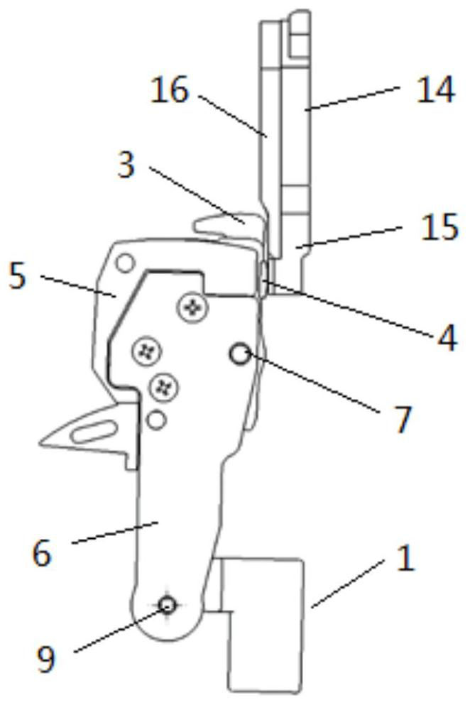
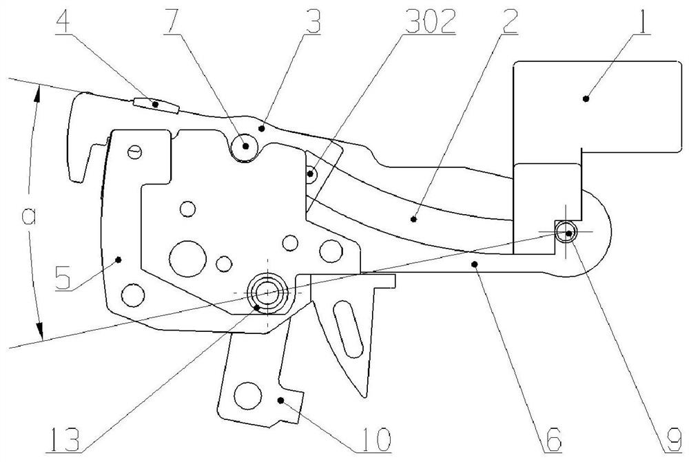
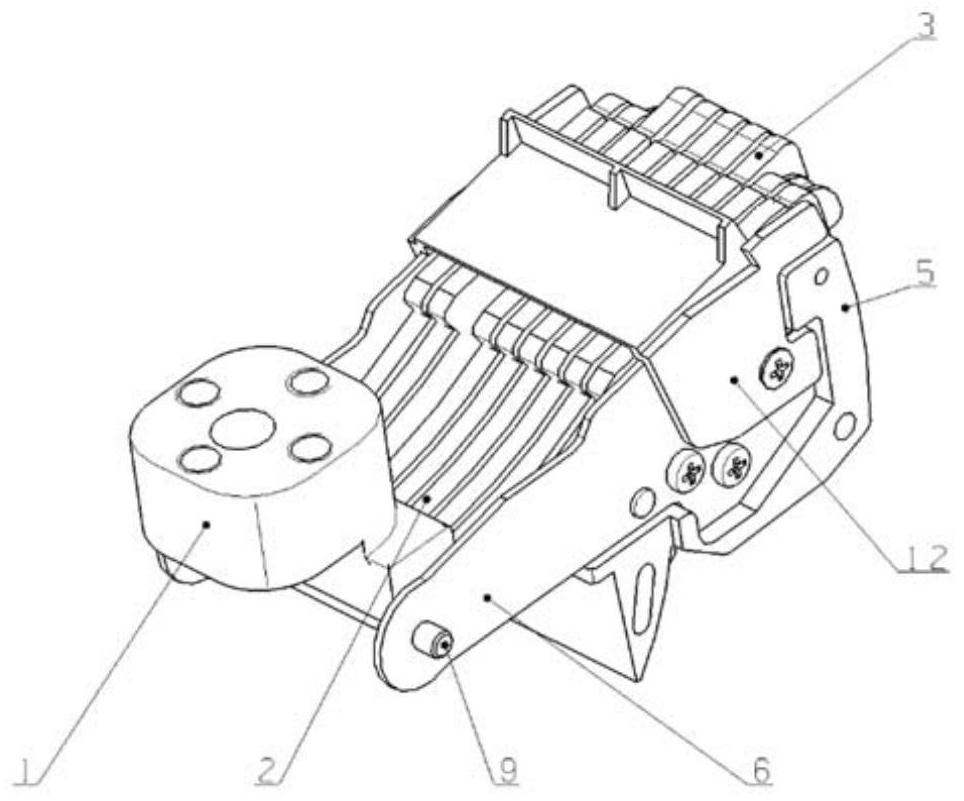
[0036] Such as Figure 1-9 As shown, a contact system of a low-voltage circuit breaker includes a moving contact system and a static contact system. The moving contact system includes a moving busbar 1, a soft connection 2, a contact piece 3, a contact support 5, a side Plate 6, first rotating shaft 7, contact spring 8, second rotating shaft 9, connecting rod 10, third rotating shaft 11, arc shield 12 and insulating liner 13; as Figure 2-3 shown.

[0037] The contact piece 3 has many pieces, and the present embodiment takes 9 pieces as an example, and the nine moving contact pieces 3 are connected side by side on the first rotating shaft 7 through the first shaft hole 303 on it and can rotate around the first The rotating shaft 7 rotates, the first rotating shaft 7 is installed on the contact support 5, and the contact spring 8 is installed on the contact support 5; the nine moving contact pieces 3 include five intermediate sequence moving contact pieces m and four pieces T...

Embodiment 2

[0045] In this embodiment, both the moving contact piece m in the middle sequence and the moving contact piece n on both sides are provided with an arc strike angle 305, and the α angle of the moving contact piece m in the middle sequence is larger than the α angle of the moving contact piece n on both sides by 1 -2 degrees, when the short circuit is broken, the arc strike angle 305 of the moving contact pieces m in the middle sequence will be disconnected from the static contact system later than the arc strike angle 305 of the moving contact pieces n on both sides. Concentrate the arc on the moving contact piece m of the intermediate sequence, and the arc quickly enters the arc extinguishing chamber along the surface of the arc leading piece 16, and the width D of the leading arc piece 16 is 2-3mm larger than the total width d of the moving contact piece m of the middle sequence . The rest of the structure of this embodiment is the same as that of Embodiment 1.


PUM


Abstract

The invention relates to a contact system of a low-voltage circuit breaker, the contact system comprises a moving contact system and a static contact system, the moving contact system comprises a plurality of moving contact blades (3), moving contacts (4), a contact support (5), a first rotating shaft (7) and a contact spring (8), the moving contacts (4) are located on the moving contact blades (3), and the moving contact blades (3) are connected to the first rotating shaft (7) side by side and can rotate around the first rotating shaft (7); the first rotating shaft (7) is mounted on a contact support (5), and a contact spring (8) is mounted on the contact support (5); the plurality of moving contact blades (3) comprise a middle sequence moving contact blade and two side moving contact blades, wherein the middle sequence moving contact blade is a moving contact blade provided with an arc striking angle (305). Compared with the prior art, the arc striking speed is high, the breaking capacity is high, the structural stability is high, and spring mounting, positioning and adjusting can be achieved.

Description

technical field [0001] The invention relates to the technical field of low-voltage electrical appliances, in particular to a contact system of a low-voltage circuit breaker. Background technique [0002] The contact system of the circuit breaker is responsible for the arduous task of normally connecting, breaking and connecting the short-circuit current. Therefore, the designed contact system should have sufficient dynamic and thermal stability, anti-welding resistance, wear resistance and temperature rise. Require. With the demand of the market, today's universal circuit breakers are widely used in the field of new energy, such as the field of photovoltaic and wind power. It is inevitable that the contact spring will deviate from the installation position during assembly, and the contact spring will also deviate from the normal use position when the switch is frequently opened and closed during use. In order to achieve the requirements of reliable breaking, short-circuit ...

Claims


Application Information

Patent Timeline
Patent Type & Authority Applications(China)
IPC IPC(8): H01H73/04H01H73/18
CPCH01H73/04H01H73/18
Inventor 徐琛君眭皓刘宗源叶心凌
Owner SHANGHAI RENMIN ELECTRICAL APP WORKS
Why Eureka
Try Eureka