Welding control method and device and terminal equipment
A control method and technology for welding conditions, applied in the field of computer readable storage media and welding control, can solve the problems of increased production cycle, low efficiency, and increased production costs of enterprises, so as to improve efficiency, speed up arc ignition, and reduce enterprise production. Effect of cycle time and production cost
- Summary
- Abstract
- Description
- Claims
- Application Information
AI Technical Summary
Problems solved by technology
Method used
Image
Examples
Embodiment 1
[0026] In the continuous spot welding process, usually in each spot welding in the continuous spot welding process, a slow wire feeding speed is used for arc ignition to improve the success rate of arc ignition. However, due to the slow wire feeding speed, the arc ignition speed of each spot welding is slow, so that the efficiency of continuous spot welding is low.
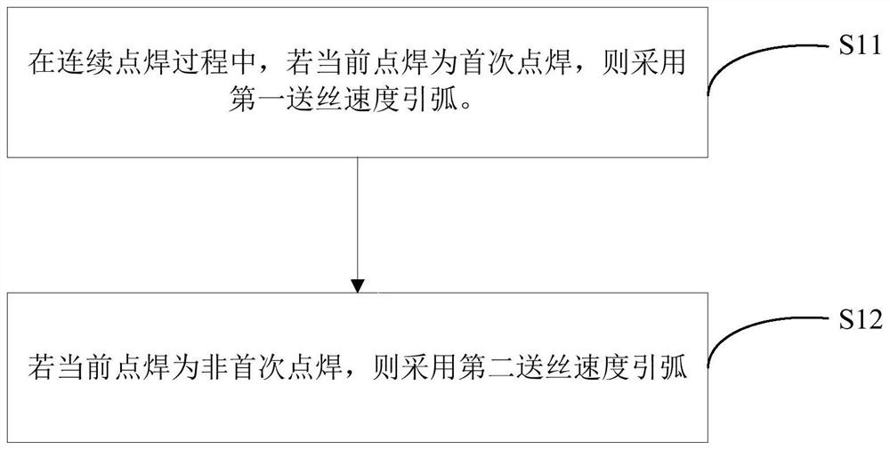
[0027] In order to improve the success rate of arc striking and the efficiency of continuous spot welding, the embodiments of the present application provide a welding control method.
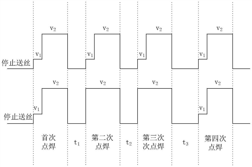
[0028] In this control method, if it is judged that the current spot welding is the first spot welding of the continuous spot welding, the set first wire feeding speed is used to start the arc, and if it is judged that the current spot welding is not the first spot welding of the continuous spot welding, A second wire feeding speed greater than the first wire feeding speed is used to start the arc.
[0029] Since spot welding has ...
Embodiment 2
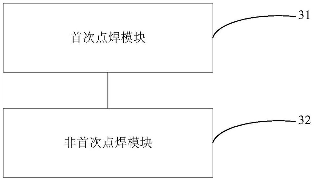
[0077] Corresponding to the above-mentioned welding control method in the above-mentioned embodiment, image 3 A block diagram of the structure of the welding control device provided by the embodiment of the present application is shown. For convenience of description, only the part related to the embodiment of the present application is shown.
[0078] refer to image 3 , the device includes: a first spot welding module 31 and a non-first spot welding module 32 . in,
[0079] The first spot welding module 31 is used to start the arc at the first wire feeding speed if the current spot welding is the first spot welding during the continuous spot welding process;
[0080] The non-first-time spot welding module 32 is used to start the arc with a second wire feeding speed if the current spot welding is not the first spot welding, wherein the second wire feeding speed is greater than the first wire feeding speed.
[0081]In the embodiment of the present application, the first sp...
Embodiment 3
[0102] Figure 4 This is a schematic structural diagram of a terminal device provided by an embodiment of the present application. like Figure 4 As shown, the terminal device 4 in this embodiment includes: at least one processor 40 ( Figure 4 only one processor is shown), a memory 41 and a computer program 42 stored in said memory 41 and executable on said at least one processor 40, said processor 40 executing said computer program 42 to achieve the above Steps in any of the various method embodiments, such as figure 1 Steps S11 to S12 are shown. Alternatively, when the processor 40 executes the computer program 42, the functions of each module / unit in the above-mentioned apparatuses are realized, such as image 3 The functions of the modules 31 to 32 are shown.
[0103] Exemplarily, the computer program 42 may be divided into one or more modules / units, and the one or more modules / units are stored in the memory 41 and executed by the processor 40 to complete the this a...
PUM
 Abstract
Description
Claims
Application Information
 - R&D
- Intellectual Property
- Life Sciences
- Materials
- Tech Scout
- Unparalleled Data Quality
- Higher Quality Content
- 60% Fewer Hallucinations
Browse by: Latest US Patents, China's latest patents, Technical Efficacy Thesaurus, Application Domain, Technology Topic, Popular Technical Reports.
© 2025 PatSnap. All rights reserved.Legal|Privacy policy|Modern Slavery Act Transparency Statement|Sitemap|About US| Contact US: help@patsnap.com


