Substrate conveying device

A transmission device and substrate technology, applied in the direction of conveyors, conveyor objects, mechanical conveyors, etc., can solve the problems of heavy substrate weight, high center of gravity, and difficulty in accurate positioning, and achieve simplified structure, light weight, and smooth movement precise effect

Pending Publication Date: 2022-03-08
SHENZHEN XINYICHANG TECH CO LTD
View PDF0 Cites 0 Cited by
  • Summary
  • Abstract
  • Description
  • Claims
  • Application Information

AI Technical Summary

Problems solved by technology

[0003] The purpose of the embodiments of the present application is to provide a substrate transfer device to solve the problem in the related art that when large-scale substrates are bonded, the transfer structure and the overall weight of the substrate are large, the center of gravity is high, and it is difficult to accurately position. It is necessary to move the die-bonding head, resulting in The problem of low efficiency

Method used


Image

  • Substrate conveying device
  • Substrate conveying device
  • Substrate conveying device

Examples


Embodiment Construction

[0036] In order to make the technical problems, technical solutions and beneficial effects to be solved by the present application clearer, the present application will be further described in detail below in conjunction with the accompanying drawings and embodiments. It should be understood that the specific embodiments described here are only used to explain the present application, and are not intended to limit the present application.

[0037] It should be noted that when an element is referred to as being “fixed” or “disposed on” another element, it may be directly on the other element or be indirectly on the other element. When an element is referred to as being "connected to" another element, it can be directly connected to the other element or indirectly connected to the other element.

[0038] In addition, the terms "first" and "second" are used for descriptive purposes only, and cannot be interpreted as indicating or implying relative importance or implicitly specify...


PUM


Abstract

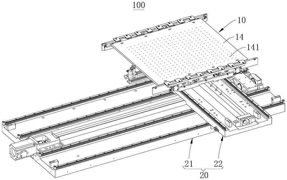
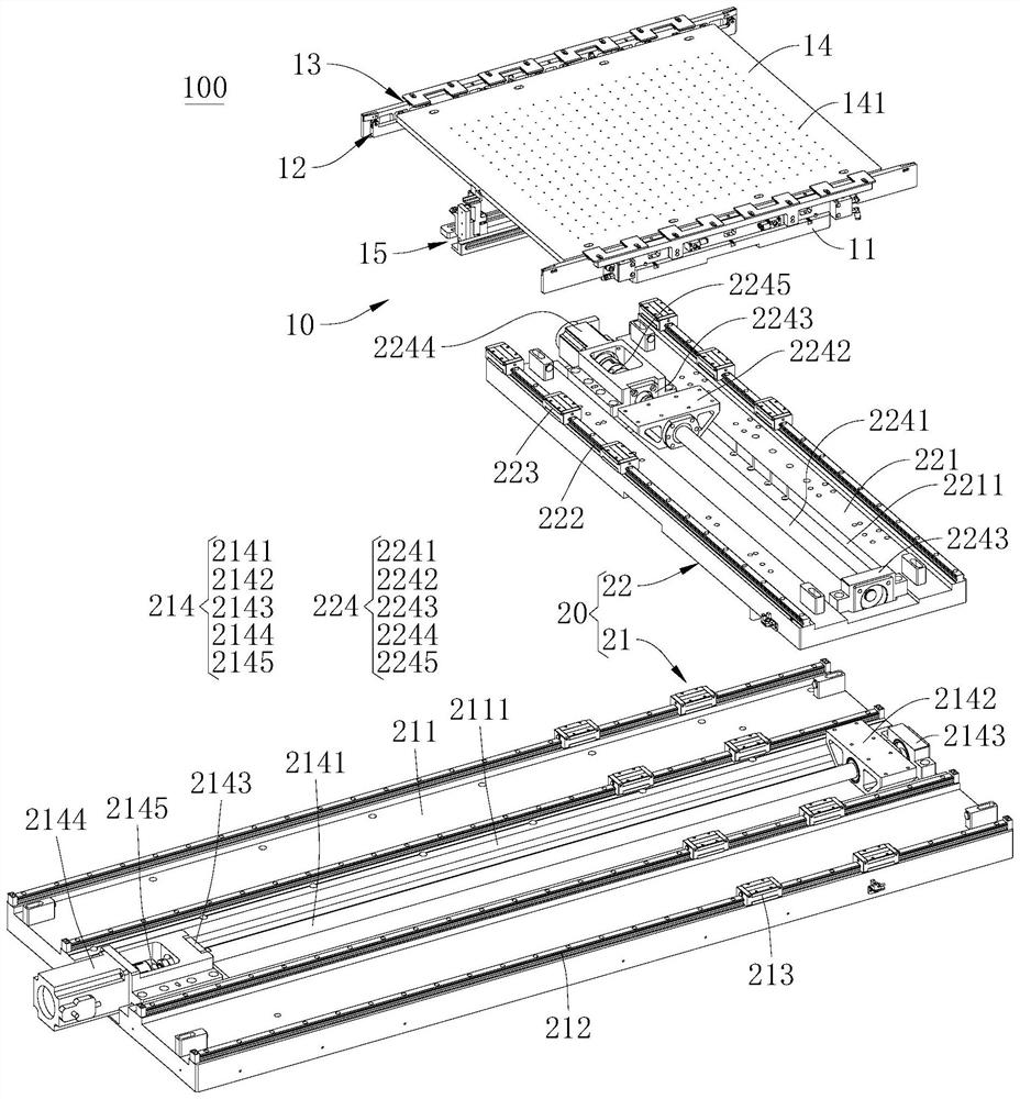
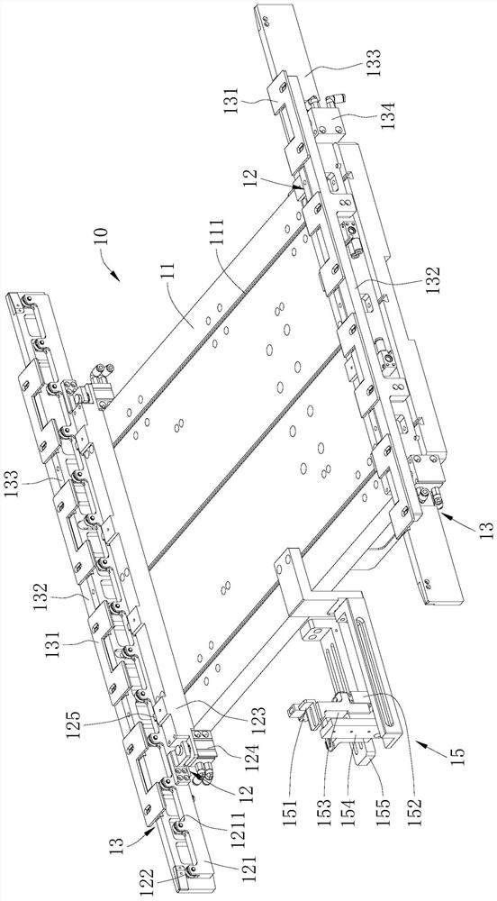
The invention provides a substrate conveying device which comprises a clamping plate mechanism and a plane moving table. The two sets of roller assemblies are used for supporting the two opposite sides of the base plate in a matched mode; and the two sets of clamping assemblies are installed on the two opposite sides of the supporting bottom plate correspondingly and used for fixing the two opposite sides of the base plate to the corresponding roller assemblies in an abutting mode, so that the clamping assemblies are matched with the corresponding roller assemblies to clamp and fix the side edges of the base plate. According to the base plate conveying device, the roller assemblies are arranged on the two sides of the supporting bottom plate correspondingly, the base plate is supported through the roller assemblies so that the gravity center height of the base plate relative to the supporting bottom plate can be reduced, the clamping assemblies are arranged to be matched with the roller assemblies to clamp and fix the base plate, and then the plane moving table can conveniently drive the clamping plate mechanism to move stably and accurately; and then the substrate is driven to move stably and accurately. Structures such as a motor and a conveying belt are not needed, the weight is lighter, the structure is more simplified and light, and the substrate is driven to move more stably and accurately.

Description

technical field [0001] The present application belongs to the technical field of crystal bonding, and more specifically relates to a substrate transfer device. Background technique [0002] When the die-bonding machine is solidifying the crystal, generally the die-bonding head will pick up the chip and install it on the substrate, which requires the substrate to be transported to the die-bonding head to install the chip on the substrate. During die bonding, it is often necessary to install multiple chips on the substrate, which requires aligning each die-bonding position on the substrate with the die-bonding head to install the chips. At present, for small substrates, the substrate is generally received and supported by a belt transfer structure, and the belt transfer structure and the substrate are driven by a planar moving table to move as a whole, so that each die-bonding position on the substrate is aligned with the die-bonding head for die-bonding. For large substrates...

Claims


Application Information

Patent Timeline
Patent Type & Authority Applications(China)
IPC IPC(8): B65G35/00B65G47/74B65G47/22
CPCB65G35/00B65G47/74B65G47/22
Inventor 黄岗曾国鹏严楚雄
Owner SHENZHEN XINYICHANG TECH CO LTD
Why Eureka
Try Eureka