Bridge crane with high-strength main beam
An overhead crane, high-strength technology, applied in the direction of walking overhead cranes, cranes, load blocks, etc., can solve the problems of inability to adjust the attitude structure of the spreader, poor flexibility in use, etc., to improve stability and firmness, strengthen Protective effect, the effect of improving the firmness of the structure
- Summary
- Abstract
- Description
- Claims
- Application Information
AI Technical Summary
Problems solved by technology
Method used
Image
Examples
Embodiment 1
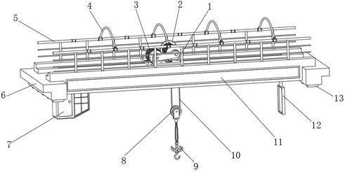
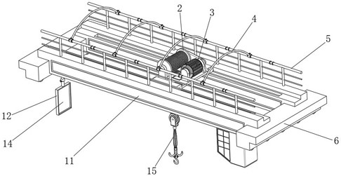
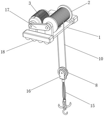
[0034] An overhead crane with a high-strength girder, such as Figure 1-7As shown, it includes a mounting base 1 and a main beam 11, a lifting mechanism is installed on the mounting base 1, first electric control wheels 18 are installed on the bottom of both sides of the mounting base 1, and a mounting base 11 is provided on the main beam 11. 1 moving track, the first electric control wheel 18 rolls in the track; the lifting mechanism includes a winding wheel 2 and a winding motor 3, and the winding wheel 2 is rotatably installed on the top of the mounting base 1, and the winding motor 3 The motor seat is installed on the top of the mounting seat 1, and the output end of the winding motor 3 is installed with the same speed reducer 17 on the rotating shaft of the winding wheel 2; the moving pulley 8 is connected to the winding wheel 2 through the first suspension rope 10 , the two sides of the movable pulley 8 are provided with the same mounting frame 16, the bottom of the moun...
Embodiment 2
[0044] An overhead crane with a high-strength girder, such as figure 2 , Figure 7 As shown, in order to facilitate observation; this embodiment makes the following improvements on the basis of Embodiment 1: the bottom of the main beam 11 is provided with a control room 7, and the bottom of the main beam 11 is equipped with an adjustable mirror frame 12, and inside the mirror frame 12 An observation mirror 14 is installed; the height of the observation mirror 14 is adapted to the control room 7; by setting the observation mirror 14 and other structures, it is convenient for the user to observe better, and the practicality is improved.
[0045] In order to facilitate the adjustment of the viewing mirror 14 angles, such as Figure 7 As shown, the bottom of the main beam 11 is fixed with a spherical seat 35 by bolts, and the outer wall of the top of the picture frame 12 is fixed with a spherical rod 34 by bolts, and the top of the spherical rod 34 rotates on the inner wall of t...
PUM
 Abstract
Description
Claims
Application Information
 - R&D
- Intellectual Property
- Life Sciences
- Materials
- Tech Scout
- Unparalleled Data Quality
- Higher Quality Content
- 60% Fewer Hallucinations
Browse by: Latest US Patents, China's latest patents, Technical Efficacy Thesaurus, Application Domain, Technology Topic, Popular Technical Reports.
© 2025 PatSnap. All rights reserved.Legal|Privacy policy|Modern Slavery Act Transparency Statement|Sitemap|About US| Contact US: help@patsnap.com


