
A Bridge Crane with High Strength Main Girder

An overhead crane, high-strength technology, applied in the direction of walking overhead cranes, cranes, load blocks, etc., can solve the problems of inability to adjust the attitude structure of the spreader, poor flexibility in use, etc., to improve stability and firmness, strengthen Protective effect, the effect of improving the firmness of the structure

Active Publication Date: 2022-04-22
江苏格雷特起重机械有限公司
View PDF6 Cites 0 Cited by
  • Summary
  • Abstract
  • Description
  • Claims
  • Application Information

AI Technical Summary

Problems solved by technology

The bridge crane in the above-mentioned patent has the following disadvantages: although it can meet certain requirements for use, it cannot adjust the posture structure of the spreader according to the actual situation when hoisting different objects, and the flexibility of use is poor, so it needs to be improved

Method used


Image

  • A Bridge Crane with High Strength Main Girder
  • A Bridge Crane with High Strength Main Girder
  • A Bridge Crane with High Strength Main Girder

Examples


Embodiment 1

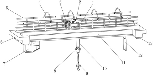
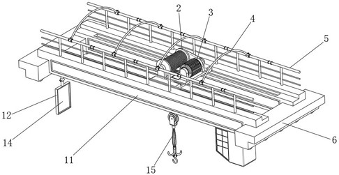
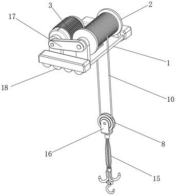
[0034] An overhead crane with a high-strength girder, such as Figure 1-7As shown, it includes a mounting base 1 and a main beam 11, a lifting mechanism is installed on the mounting base 1, first electric control wheels 18 are installed on the bottom of both sides of the mounting base 1, and a mounting base 11 is provided on the main beam 11. 1 moving track, the first electric control wheel 18 rolls in the track; the lifting mechanism includes a winding wheel 2 and a winding motor 3, and the winding wheel 2 is rotatably installed on the top of the mounting base 1, and the winding motor 3 The motor seat is installed on the top of the mounting seat 1, and the output end of the winding motor 3 is installed with the same speed reducer 17 on the rotating shaft of the winding wheel 2; the moving pulley 8 is connected to the winding wheel 2 through the first suspension rope 10 , the two sides of the movable pulley 8 are provided with the same mounting frame 16, the bottom of the moun...

Embodiment 2

[0044] An overhead crane with a high-strength girder, such as figure 2 , Figure 7 As shown, in order to facilitate observation; this embodiment makes the following improvements on the basis of Embodiment 1: the bottom of the main beam 11 is provided with a control room 7, and the bottom of the main beam 11 is equipped with an adjustable mirror frame 12, and inside the mirror frame 12 An observation mirror 14 is installed; the height of the observation mirror 14 is adapted to the control room 7; by setting the observation mirror 14 and other structures, it is convenient for the user to observe better, and the practicality is improved.

[0045] In order to facilitate the adjustment of the viewing mirror 14 angles, such as Figure 7 As shown, the bottom of the main beam 11 is fixed with a spherical seat 35 by bolts, and the outer wall of the top of the picture frame 12 is fixed with a spherical rod 34 by bolts, and the top of the spherical rod 34 rotates on the inner wall of t...


PUM


Abstract

The invention discloses a bridge crane with a high-strength main girder, which relates to the technical field of bridge cranes; in order to improve the flexibility of use; it specifically includes a mounting base and a main beam, and a lifting mechanism is installed on the mounting base. The first electric control wheel is installed on the bottom of both sides of the seat, and the main beam is provided with a track for the installation seat to move, and the first electric control wheel rolls in the track; the lifting mechanism includes a winding wheel and a winding motor, and the winding The wheel is rotatably mounted on top of the mount. According to the actual situation, the present invention can disassemble and use the four second hooks by setting the second hooks, the first hooks and other structures, and carry out hoisting in a four-point hoisting manner, and can also connect the four hooks according to requirements. The seat is combined together, and the connecting head is inserted into the four arc-shaped grooves, and then the first connecting pin and the second connecting pin are inserted in turn for fixing, so as to achieve the purpose of combining the second hook with the first hook. One hook is used for hoisting, which improves the flexibility of use.

Description

technical field [0001] The invention relates to the technical field of bridge cranes, in particular to a bridge crane with a high-strength main girder. Background technique [0002] The bridge crane is a lifting device that is placed horizontally over the workshop, warehouse and stockyard for material lifting. It is the most widely used and the largest number of lifting machinery; its two ends are located on tall cement columns or metal supports. , shaped like a bridge; the bridge frame of the bridge crane runs longitudinally along the tracks laid on the elevated sides on both sides, which can make full use of the space under the bridge frame to lift materials without being hindered by ground equipment; although the current bridge cranes can meet certain requirements Use requirements, but when lifting different objects, the attitude structure of the spreader cannot be adjusted according to the actual situation, and the flexibility of use is poor, so it needs to be improved. ...

Claims


Application Information

Patent Timeline
Patent Type & Authority Patents(China)
IPC IPC(8): B66C17/00B66C11/02B66C1/14B66C13/00
CPCB66C17/00B66C11/02B66C1/14B66C13/00
Inventor 王志峰陈彦明
Owner 江苏格雷特起重机械有限公司
Learn More