Hydraulic engineering flood prevention device and using method thereof

A technology for flood control devices and water conservancy projects, applied in water conservancy projects, sea area projects, dikes, etc., can solve the problems of flood control plate toppling and low bearing capacity, and achieve the effects of reducing impact, improving stability, and increasing impact resistance

Active Publication Date: 2022-03-08
WATER RESOURCES RES INST OF SHANDONG PROVINCE
View PDF4 Cites 1 Cited by
  • Summary
  • Abstract
  • Description
  • Claims
  • Application Information

AI Technical Summary

Problems solved by technology

However, when the existing flood control boards are in use, their bearing capacity is low, and they cannot bear the impact of large water flow, and the flood control board is prone to be dumped due to the impact of large water flow

Method used


Image

  • Hydraulic engineering flood prevention device and using method thereof
  • Hydraulic engineering flood prevention device and using method thereof
  • Hydraulic engineering flood prevention device and using method thereof

Examples


Embodiment 1

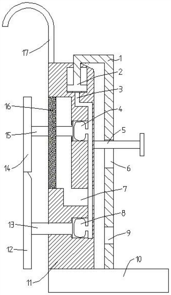
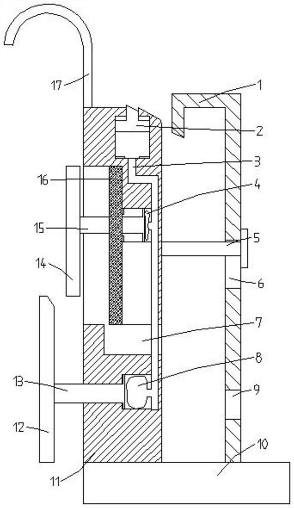
[0035] Such as Figure 1-2 As shown, this embodiment proposes a flood control device for water conservancy projects, including a water retaining mechanism 19, and also includes a plurality of unloading mechanisms 18 arranged in front of the water retaining mechanism 19; Flood protection device. The water retaining mechanism 19 can be a commonly used flood control plate in the prior art, and can also be other water retaining devices, which will not be described in detail.

[0036] Below with regard to above-mentioned unloading mechanism 18, be described in further detail:

[0037] The unloading mechanism 18 comprises a base 10, and the top of the base 10 is connected with an unloading wall 11; one side of the unloading wall 11 is provided with an upper movable plate 14 and a lower movable plate 12 arranged up and down, and the unloading wall 11 is provided with a sliding cavity, and the sliding The cavity is sealed and slidably connected with a sealing plate 16; the upper mov...

Embodiment 2

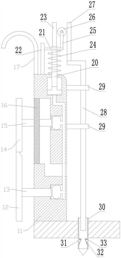
[0044] Such as Figure 3-4 As shown, this embodiment proposes a flood control device for water conservancy projects. Other structures are the same as in Embodiment 1. The difference is that the stabilizing component adopts another structural form, which includes a moving rod 20, a moving rod 20 and a lifting block 2 The top is connected; the top of the unloading wall 11 is also connected with a horizontal plate 21, specifically, the horizontal plate 21 is connected with the unloading wall 11 through a column 22; the moving rod 20 is slidingly connected with the horizontal plate 21, and the moving rod 20 can move along the horizontal plate 21 slides up and down; the moving rod 20 is provided with a first spring 24, the top of the first spring 24 is connected with the horizontal plate 21, and the bottom end of the first spring 24 is connected with the moving rod 20; the top of the moving rod 20 is connected with the first tooth A bar 23, a gear 26 is meshed on one side of the fi...

Embodiment 3

[0049] Such as Figure 5 As shown, this embodiment proposes a flood control device for water conservancy projects. Other structures are the same as in Embodiment 2, the difference is that a support 34 is connected to the top of the base 10, and a diagonal brace 35 is hinged on the top of the support 34. Above the base 10 Also be connected with wheel frame 36, wheel frame 36 top rotations are connected with pulley 37, hang and be connected with stay cord 38 on pulley 37, one end of stay cord 38 links to each other with diagonal strut 35, and the other end of described stay cord 38 is connected with all The connecting rod 28 is connected.

[0050] For example, the method for using the flood control device for water conservancy projects in this embodiment includes the following steps:

[0051] Water retaining mechanism 19 is installed, and unloading mechanism 18 is installed in the place ahead of water retaining mechanism 19; The lower movable rod 13 and the upper movable rod 1...


PUM


Abstract

The invention provides a water conservancy project flood prevention device and a using method thereof. The water conservancy project flood prevention device comprises a water retaining mechanism and a force unloading mechanism. The force unloading mechanism comprises a base, the base is connected with a force unloading wall, the force unloading wall is provided with an upper movable plate and a lower movable plate, the force unloading wall is provided with a sliding cavity, and a sealing plate is slidably connected into the sliding cavity; the upper movable plate is connected with an upper movable rod, and the upper movable rod is connected with the sealing plate; the unloading wall is further provided with a first sliding hole. One end of the upper movable rod penetrates through the sliding cavity and enters the first sliding hole; an upper air bag is mounted in the first sliding hole; the unloading wall is also provided with a drainage hole; a second sliding hole is formed below the sliding cavity, and a lower air bag is arranged in the second sliding hole; the lower movable plate is connected with a lower movable rod, and the other end of the lower movable rod enters the second sliding hole. An air path is arranged in the unloading wall, and the upper air bag and the lower air bag are connected with the air path; a third sliding hole is formed in the top of the unloading wall, and a lifting block is slidably connected into the third sliding hole. The lifting block is in linkage connection with a stabilizing assembly. The device is good in stability and capable of effectively weakening impact force of water flow.

Description

technical field [0001] The invention belongs to the technical field of water conservancy engineering, and in particular relates to a flood control device for water conservancy engineering and an application method thereof. Background technique [0002] Flood control is mainly to prevent or mitigate flood disasters. During the flood season, various measures of the flood control system are used for protection and dispatch, and the work of flood defense is carried out. In order to ensure the safety of people's life and property in the district, flood control boards are often used during flood control. However, when the existing flood control boards are in use, their bearing capacity is low, and they cannot bear the impact of relatively large water flow. Therefore, it is necessary to improve. Contents of the invention [0003] In order to solve the above-mentioned problems in the prior art, a flood control device for water conservancy projects and a method for using the same...

Claims


Application Information

Patent Timeline
Patent Type & Authority Applications(China)
IPC IPC(8): E02B3/10
CPCE02B3/10E02B3/104Y02A10/11
Inventor 刘莉莉宋苏林程素珍黄继文刘英昊杨大伟郝晓辉王光辉巩向锋王锐徐运海张立华董新美崔春梅
Owner WATER RESOURCES RES INST OF SHANDONG PROVINCE
Why Eureka
Try Eureka