
Monitoring rod with height convenient to adjust and capable of freely rotating

A height-adjustable and free technology, applied in the field of monitoring rods, can solve the problems of excessive structure, inability to adjust the height and angle of the camera device, and reduce the practicality and flexibility of monitoring rods, so as to achieve the advantages of simple operation, convenient power acquisition and reduced cost Effect

Pending Publication Date: 2022-03-08
JIANGXI PROVINCE POST & TELECOMM CONSTR PROJECTS CO LTD
View PDF0 Cites 0 Cited by
  • Summary
  • Abstract
  • Description
  • Claims
  • Application Information

AI Technical Summary

Problems solved by technology

[0003] The structure of the existing monitoring pole is too traditional. During use, it is impossible to adjust the height and angle of the camera device, which reduces the practicality and flexibility of the monitoring pole, affects the normal progress of the camera work, and brings difficulties to the relevant staff. It has brought great inconvenience, therefore, for the above current situation, it is urgent to develop a monitoring rod that is convenient for height adjustment and can rotate freely, so as to overcome the deficiencies in current practical applications.

Method used


Image

  • Monitoring rod with height convenient to adjust and capable of freely rotating
  • Monitoring rod with height convenient to adjust and capable of freely rotating
  • Monitoring rod with height convenient to adjust and capable of freely rotating

Examples


Embodiment Construction

[0025] The technical solutions in the embodiments of the present invention will be clearly and completely described below in conjunction with the accompanying drawings in the embodiments of the present invention. Obviously, the described embodiments are only some, not all, embodiments of the present invention. Based on the embodiments of the present invention, all other embodiments obtained by persons of ordinary skill in the art without creative efforts fall within the protection scope of the present invention.

[0026] The specific implementation of the present invention will be described in detail below in conjunction with specific embodiments.

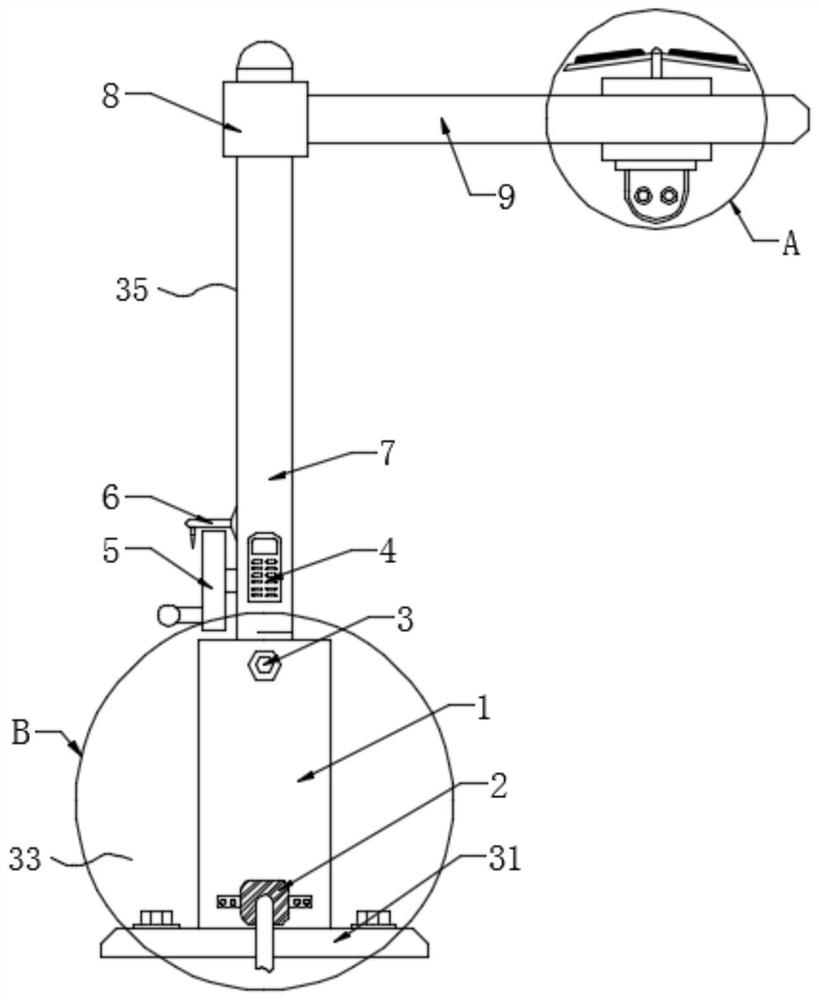
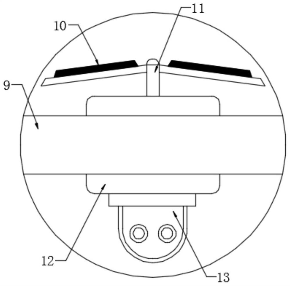
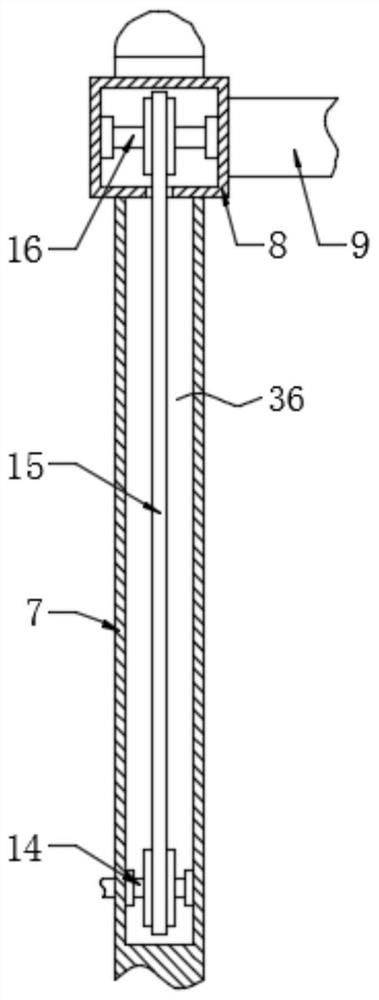
[0027] see Figure 1-8 , a freely rotatable monitoring pole that is convenient for height adjustment provided by an embodiment of the present invention includes a support pole 1 and a mounting base 31 for fixing the support pole 1, and also includes:

[0028] Lifting mechanism 33, described lifting mechanism 33 is connected with d...


PUM


Abstract

The invention relates to the technical field of monitoring rods, in particular to a monitoring rod convenient in height adjustment and capable of rotating freely, which comprises a support rod and a mounting base, and further comprises a lifting mechanism connected with the support rod; wherein the lifting mechanism comprises a pressurizing assembly and a lifting pipe; the translation frame is connected with the lifting pipe through an adapter block; the adjusting mechanism is positioned on the translation frame; wherein the adjusting mechanism comprises a translation assembly and an angle adjusting assembly, the translation assembly comprises a driving unit and a sliding column, and the angle adjusting assembly comprises a camera, a first adsorption part, a rotating disc, a second adsorption part and a placing cavity. The working state of the camera can be flexibly adjusted, the practicability and flexibility of the equipment are improved, and convenience is brought to monitoring work.

Description

technical field [0001] The invention relates to the technical field of monitoring poles, in particular to a freely rotatable monitoring pole which is convenient for height adjustment. Background technique [0002] The monitoring pole is also called the monitoring pole, which is the carrier of the surveillance camera. It is divided into octagonal monitoring pole, round tube monitoring pole, equal-diameter monitoring pole, variable-diameter monitoring pole and tapered monitoring pole. The height is generally 3-6 meters, mainly located in Traffic roads, intersections, schools, governments, communities, factories, border defense and airports and other places that need surveillance cameras, the use of surveillance poles improves urban security and is an effective guarantee for residents' lives. [0003] The structure of the existing monitoring pole is too traditional. During use, it is impossible to adjust the height and angle of the camera device, which reduces the practicality ...

Claims


Application Information

Patent Timeline
Patent Type & Authority Applications(China)
IPC IPC(8): F16M11/04F16M11/08F16M11/18F16M11/28
CPCF16M11/043F16M11/28F16M11/045F16M11/18F16M11/08
Inventor 徐仁贵赖怡华方毅斌
Owner JIANGXI PROVINCE POST & TELECOMM CONSTR PROJECTS CO LTD
Learn More