

Safety sign convenient to disassemble and maintain for rail transit
A rail transit and signage technology, applied in the field of rail transit, can solve the problems of increasing the carrying load and troublesome of the staff, and achieve the effect of increasing the carrying load and facilitating disassembly and maintenance.
- Summary
- Abstract
- Description
- Claims
- Application Information
AI Technical Summary
Problems solved by technology
Method used
Image

Examples
Embodiment Construction
[0016] In order to make the object, technical solution and advantages of the present invention clearer, the present invention will be further described in detail below in conjunction with the accompanying drawings and embodiments. It should be understood that the specific embodiments described here are only used to explain the present invention, not to limit the present invention.
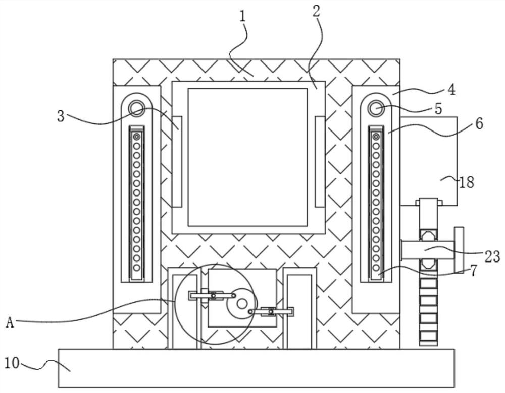
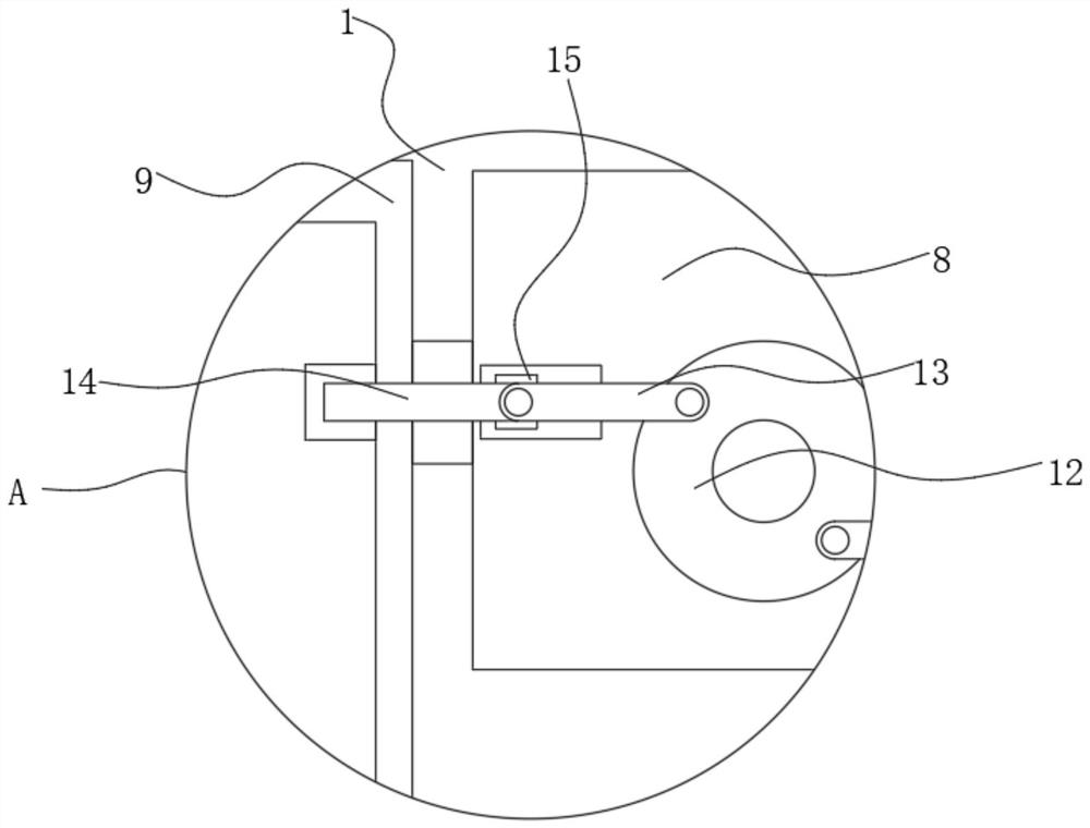
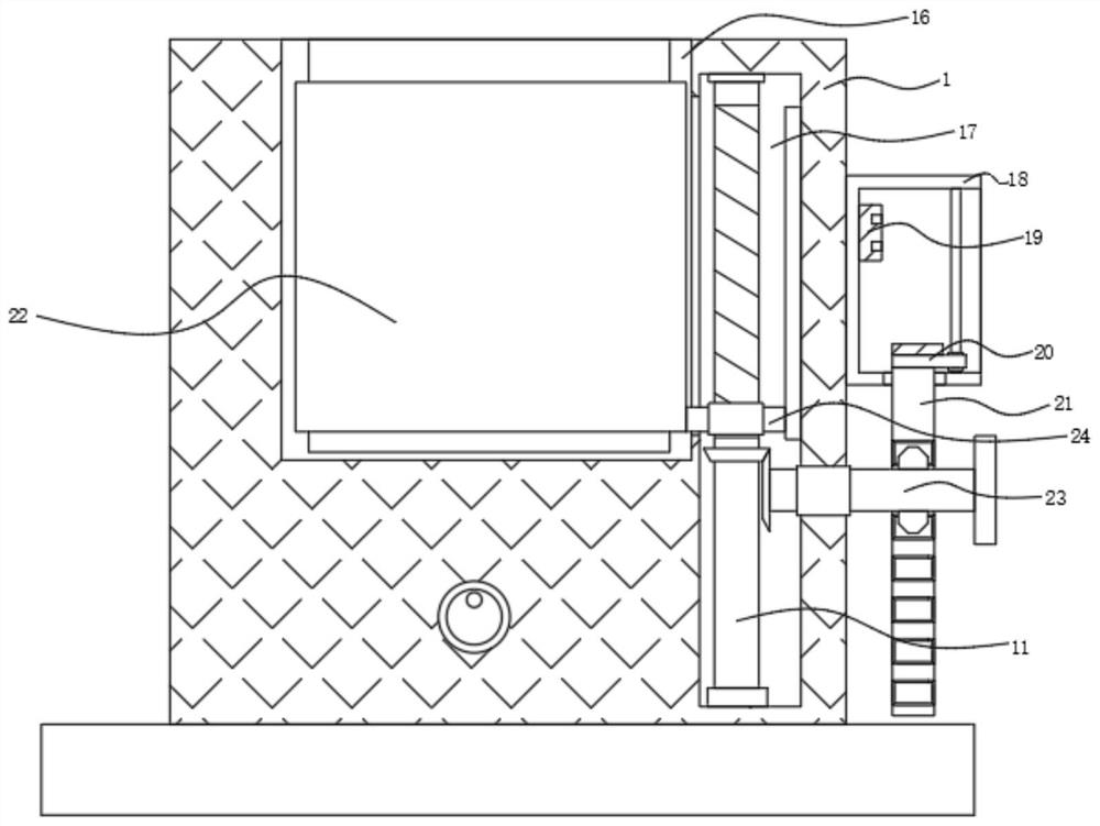
[0017] see Figure 1-3 , the present invention provides a technical solution: a safety sign for rail transit that is easy to disassemble and maintain, comprising a device housing 1 with an open front end, and a working chamber 2 inside the device housing 1 .
[0018] The working chamber 2 communicates with the opening of the front end of the device housing 1, so that the display board inside the working chamber 2 can be displayed.
[0019] Both sides inside the working chamber 2 are provided with lighting strips 3 , and the inside of the working chamber 2 is provided with a display board.
[0020...
PUM
 Abstract
Description
Claims
Application Information