
Inflation mechanism

An inflatable channel and gas injection technology, which is applied in the direction of inflatable valves, machine/structural component testing, mechanical equipment, etc., can solve the problems of difficult processing, quantification of leak rate, large interference, etc., and achieve improved sealing performance , reliable sealing performance and simple manual operation

Pending Publication Date: 2022-03-11
上海贤日测控科技有限公司
View PDF0 Cites 0 Cited by
  • Summary
  • Abstract
  • Description
  • Claims
  • Application Information

AI Technical Summary

Problems solved by technology

[0003] The existing detection method is water detection, which is to weld the nozzle of the container, soak it in water as a whole, observe whether there are bubbles, and then cut it off after the detection is completed. This detection method is greatly disturbed by human beings, and the leakage rate cannot be quantified. , and the sealing device of the water test cannot be used on the helium test device, and its processing is difficult and the cost is high

Method used


Image

  • Inflation mechanism
  • Inflation mechanism
  • Inflation mechanism

Examples


Embodiment Construction

[0039] In order to make the purpose, technical solutions and advantages of the embodiments of the present invention more clear, various implementation modes of the present invention will be described in detail below in conjunction with the accompanying drawings. However, those of ordinary skill in the art can understand that, in each implementation manner of the present invention, many technical details are provided for readers to better understand the present application. However, even without these technical details and various changes and modifications based on the following implementation modes, the technical solution claimed in this application can also be realized.

[0040] In the following description, for the purposes of explaining the various disclosed embodiments, certain specific details are set forth in order to provide a thorough understanding of the various disclosed embodiments. One skilled in the relevant art will recognize, however, that an embodiment may be p...


PUM


Abstract

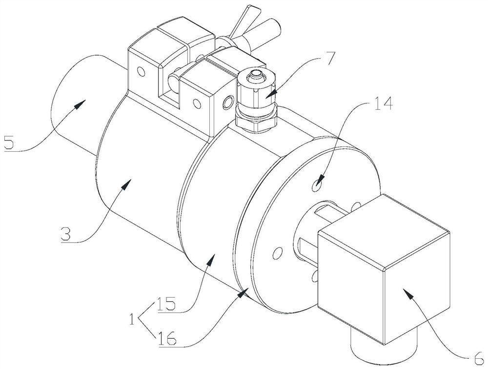
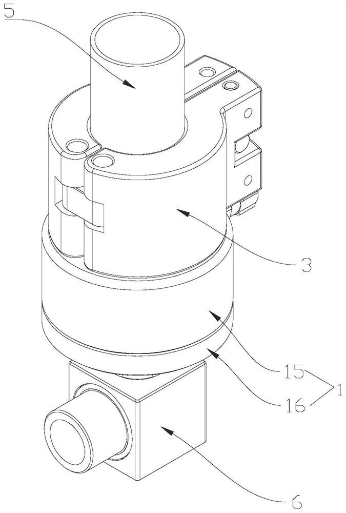
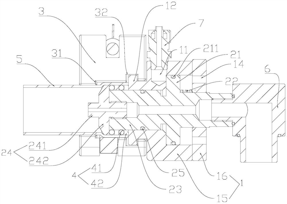
The invention discloses an air inflation mechanism which comprises a valve body, a valve rod, a valve rod and a valve rod. The valve element is slidably located in the mounting channel in the axis direction of the valve body, an inflation channel penetrating through the valve element is formed in the valve element, and the far end of the valve element is exposed out of the valve body; the hoop is operably hooped outside the far end of the valve core and the far end of the valve body; the sealing piece is arranged outside the far end of the valve element in a sleeving mode, and the sealing piece is operably abutted against the end face of the far end of the valve body and the valve element in the axis direction of the valve body; the valve body is provided with a gas injection channel, a part of the valve element is communicated with the gas injection channel, and the part, communicated with the gas injection channel, of the valve element is located on the side, close to the near end of the valve element, of the gas injection channel. The sealing device has the beneficial technical effects of convenience in operation, cost reduction and reliable sealing performance.

Description

technical field [0001] The embodiments of the present invention relate to the technical field of sealing, and in particular to an inflation mechanism. Background technique [0002] In the prior art, for the helium-filled vacuum helium test at the nozzle of the container, the airtightness of the nozzle is tested. In order to realize the detection of the nozzle, the diameter of the nozzle of the container to be detected needs to be sealed for filling. [0003] The existing detection method is water detection, which is to weld the nozzle of the container, soak it in water as a whole, observe whether there are bubbles, and then cut it off after the detection is completed. This detection method is greatly disturbed by human beings, and the leakage rate cannot be quantified. , and the sealing device of the water test cannot be used on the helium test device, and its processing is relatively difficult and the cost is high. Therefore, particularly need a kind of new sealing mode, ...

Claims


Application Information

Patent Timeline
IPC IPC(8): F16K24/06F16L21/06F16L55/07F16L55/11G01M3/02
CPCF16K24/06F16L21/06F16L55/07F16L55/11G01M3/022
Inventor 张和毅
Owner 上海贤日测控科技有限公司
Learn More