Unmanned aerial vehicle inclined aerial survey image control point identification layout method and inclined aerial survey method

A technology for image control points and unmanned aerial vehicles, which is applied in the field of remote sensing surveying and mapping, can solve the problems of relying on manual extraction of pixel coordinates of image control points, affecting the accuracy of 3D model results, and position deviation of puncture points. low cost effect

Pending Publication Date: 2022-03-11
SHANGHAI GEOTECHN INVESTIGATIONS & DESIGN INST
View PDF5 Cites 0 Cited by
  • Summary
  • Abstract
  • Description
  • Claims
  • Application Information

AI Technical Summary

Problems solved by technology

Because UAV oblique photogrammetry adds a side-view lens on the basis of conventional photogrammetry, it is difficult to identify the corner points of traditional ground image control points under oblique viewing angles, resulting in positional deviation of puncture points, which ultimately affects the accuracy of 3D model results.
At the same time, the pixel coordinates of image control points are largely dependent on manual extraction, and the degree of automation is low.
Manual extraction is inefficient in a large number of photos

Method used


Image

  • Unmanned aerial vehicle inclined aerial survey image control point identification layout method and inclined aerial survey method
  • Unmanned aerial vehicle inclined aerial survey image control point identification layout method and inclined aerial survey method
  • Unmanned aerial vehicle inclined aerial survey image control point identification layout method and inclined aerial survey method

Examples


Embodiment

[0031] Embodiment: This embodiment provides a method for laying out control point marks for inclined aerial survey images of UAVs, which includes:

[0032] (S1) Insert measuring nails on the ground surface of the image control point, and measure the three-dimensional coordinates of the measuring nails; in this step, conventional means such as RTK or total station are used to measure the three-dimensional coordinates of the measuring nails.

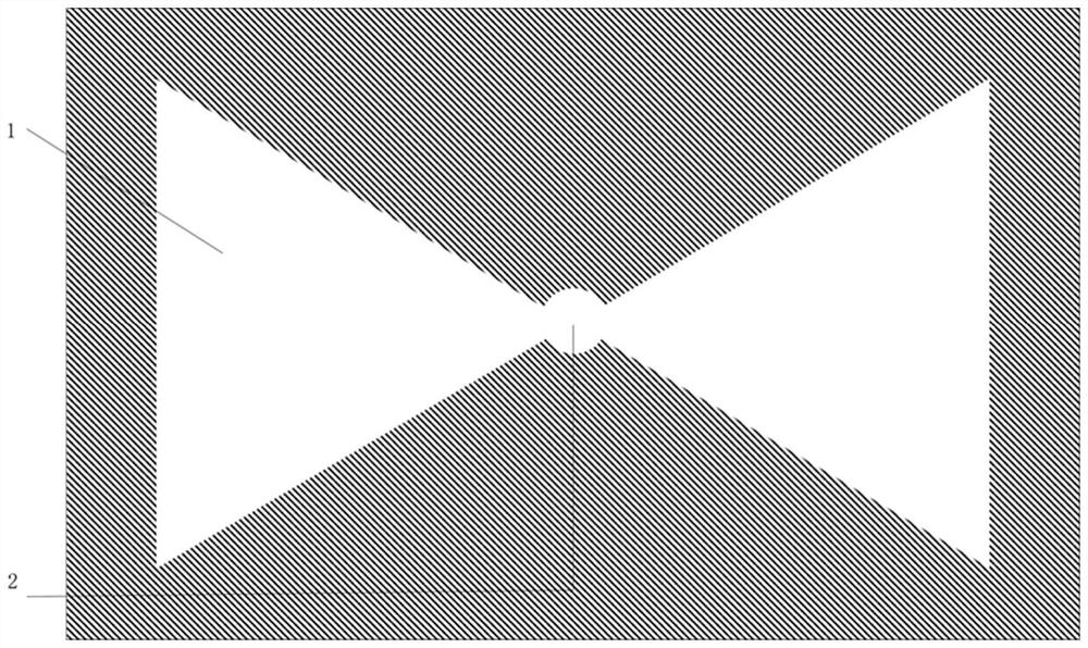
[0033] (S2) Setting such as figure 1 The shown mask has a hollowed-out area, the hollowed-out area includes a circular hollowed-out area 2 adapted to the nail and two triangular hollowed-out areas 1 symmetrically distributed on both sides of the circular hollow; and making The circular hollow area is nested with the nail. In this embodiment, the shapes of the two triangular hollow areas are congruent isosceles triangles. The opposite vertices of the two triangular hollow areas coincide with the center of the circular hollow area. The tw...


PUM


Abstract

The invention discloses an unmanned aerial vehicle inclined aerial survey image control point identification laying method and an inclined aerial survey method.The image control point identification laying method comprises the steps that (S1) a measuring nail is inserted into the ground surface of an image control point, and the three-dimensional coordinate of the measuring nail is measured; (S2) arranging a mask plate with a hollowed-out area on the image control point, wherein the hollowed-out area comprises a circular hollowed-out area matched with the measuring nail and two triangular hollowed-out areas symmetrically distributed on the two sides of the circular hollowed-out area; the measuring nail is nested in the circular hollow area; and (S3) paint spraying is carried out on the hollow-out area, so that an image control point mark is formed around the measuring nail. The identification pattern is reasonable and simple in structure, and the combination of triangles and circles is convenient for a deep learning model to identify.

Description

technical field [0001] The invention belongs to the field of remote-sensing surveying and mapping, and in particular relates to a method for arranging control point marks of tilted aerial survey images of unmanned aerial vehicles and a tilted aerial survey method. Background technique [0002] According to the UAV oblique photogrammetry technology, a certain number of image control points need to be arranged in the survey area. The image control points are the basis for the aerial three-dimensional calculation and encryption in the aerial survey industry, and directly affect the accuracy of the output results. In the process of data processing, the accuracy can be effectively improved through accurate pricking work. Because UAV oblique photogrammetry adds a lens with a side-view perspective on the basis of conventional photogrammetry, it is difficult to identify the corner points of the traditional ground image control points under the oblique perspective, resulting in posit...

Claims


Application Information

Patent Timeline
Patent Type & Authority Applications(China)
IPC IPC(8): G01C11/04G01C11/00
CPCG01C11/04G01C11/00
Inventor 郭春生王令文刘翰琪王维刘蝶赵瑞杰
Owner SHANGHAI GEOTECHN INVESTIGATIONS & DESIGN INST
Why Eureka
Try Eureka