Typical high-precision radar structure precision design and implementation method
A technology of precision design and implementation method, applied to radio wave measurement systems, instruments, etc., can solve the problems of reducing the implementation cost, low sidelobe level of radar, pointing accuracy, etc.
- Summary
- Abstract
- Description
- Claims
- Application Information
AI Technical Summary
Problems solved by technology
Method used
Image

Examples
Embodiment Construction
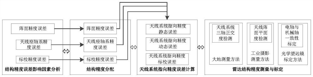
[0021] The invention is a typical high-precision radar structure precision design and implementation method, which performs structure precision distribution, antenna system pointing precision calculation, structure precision measurement and correction, and realizes matching of high-precision radar structure precision with telecommunication indicators.
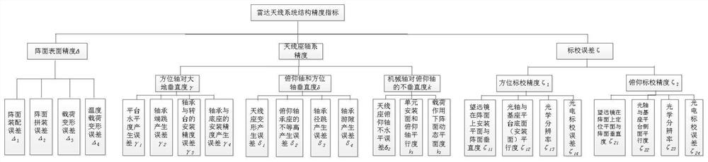
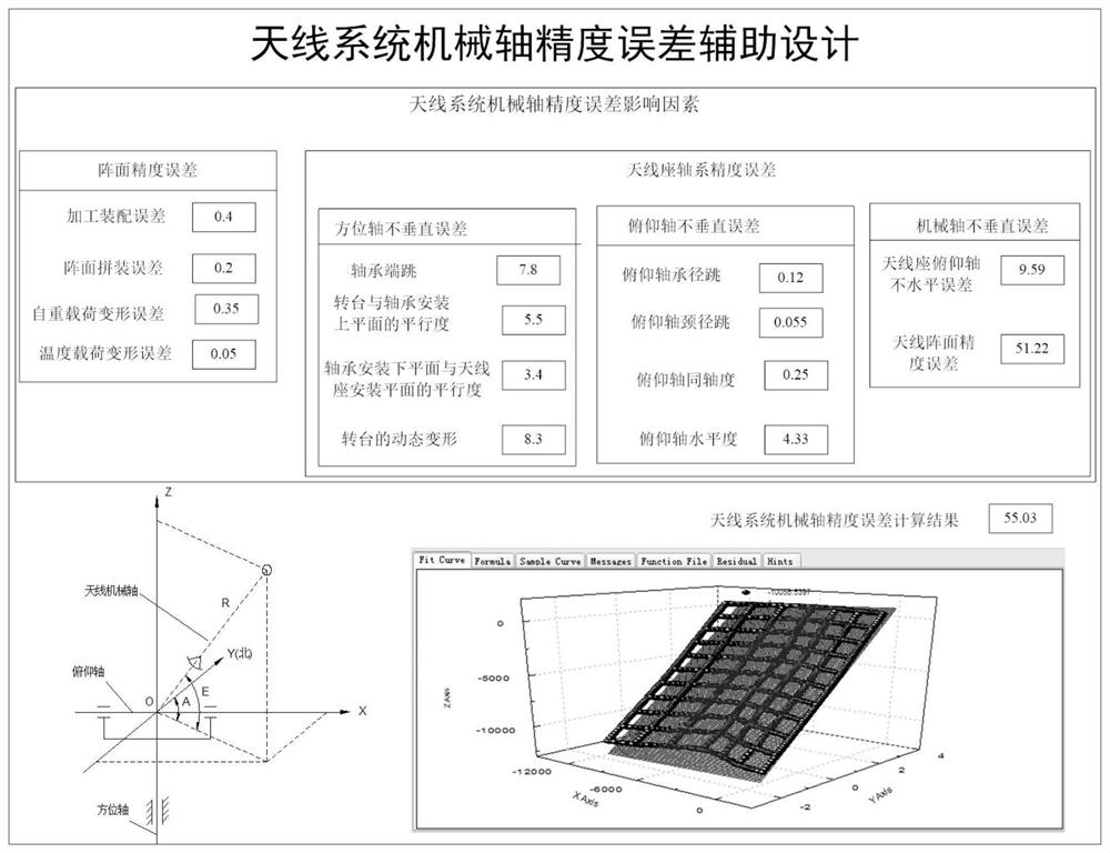
[0022] The method of this embodiment includes analysis of influencing factors of structural accuracy errors, allocation of structural accuracy, calculation of pointing accuracy errors of antenna systems, measurement and calibration of structural accuracy. Through the design and implementation method of typical high-precision radar structure precision, accurate rigidity calculation, reasonable precision distribution and precision measurement can be carried out for radar antenna, antenna transmission and servo transmission mechanism, and the balanced design of structure precision and telecommunication precision can be realized. At...
PUM
 Abstract
Description
Claims
Application Information
 - Generate Ideas
- Intellectual Property
- Life Sciences
- Materials
- Tech Scout
- Unparalleled Data Quality
- Higher Quality Content
- 60% Fewer Hallucinations
Browse by: Latest US Patents, China's latest patents, Technical Efficacy Thesaurus, Application Domain, Technology Topic, Popular Technical Reports.
© 2025 PatSnap. All rights reserved.Legal|Privacy policy|Modern Slavery Act Transparency Statement|Sitemap|About US| Contact US: help@patsnap.com