
Oblique image lens

A lens, lens technology, used in optical components, optics, instruments, etc., can solve problems such as defocusing in the field of view and imaging deformation

Pending Publication Date: 2022-03-11
HUBEI UNIV FOR NATITIES
View PDF0 Cites 0 Cited by
  • Summary
  • Abstract
  • Description
  • Claims
  • Application Information

AI Technical Summary

Problems solved by technology

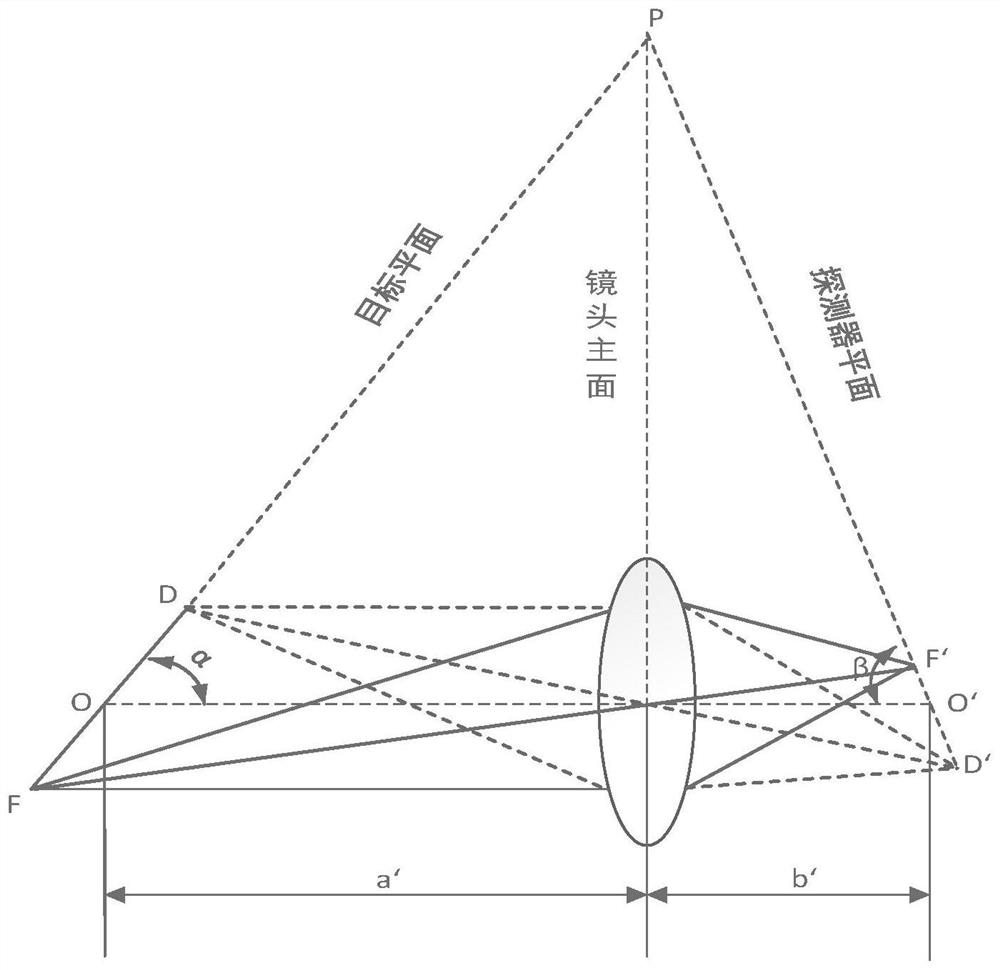
[0003] Since 3D projection detection technology requires a lens to capture an oblique target object, and the traditional lens due to the imaging rule of large and small images and the limitation of depth of field, it will cause imaging distortion and partial out-of-focus phenomena within the field of view, making it difficult to fully detect the oblique target object. Clear vision

Method used


Image

  • Oblique image lens
  • Oblique image lens
  • Oblique image lens

Examples


Embodiment Construction

[0024] In order to enable those skilled in the art to better understand the solution of the present application, the technical solution in the embodiment of the application will be clearly and completely described below in conjunction with the accompanying drawings in the embodiment of the application. Obviously, the described embodiment is only It is a part of the embodiments of this application, not all of them. Based on the embodiments in this application, all other embodiments obtained by persons of ordinary skill in the art without making creative efforts belong to the scope of protection of this application.

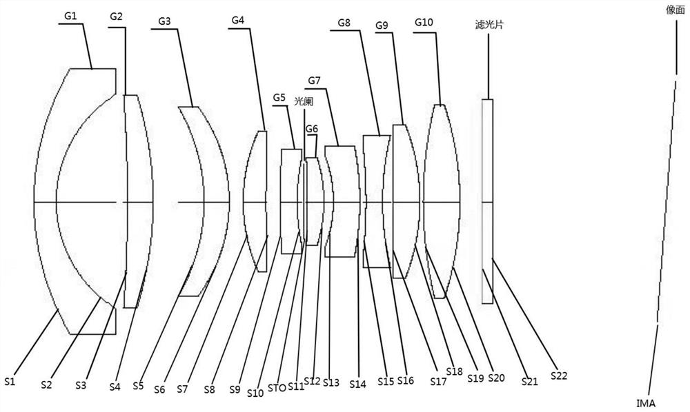
[0025] see figure 1 , figure 1 It is a schematic structural diagram of an embodiment of an oblique image lens for imaging a full field of view of an oblique target in this application, as shown in figure 1 as shown, figure 1 Include:

[0026] A first lens, a second lens, a third lens, a fourth lens, a fifth lens, a diaphragm, a sixth lens, a seventh lens, an ei...


PUM


Abstract

The invention discloses an oblique image lens which comprises a first lens to a tenth lens and an optical filter which are arranged in sequence, and a diaphragm is located between a fifth lens and a sixth lens; wherein the first lens, the second lens and the third lens form local symmetry, the fourth lens, the fifth lens, the sixth lens and the seventh lens form local symmetry, and the eighth lens, the ninth lens and the tenth lens form local symmetry, so that distortion equiaxial aberration is corrected; the diaphragm is positioned in the center of the lens, so that off-axis aberration such as field curvature can be well corrected; the fourth lens, the fifth lens, the eighth lens and the ninth lens can also help to correct astigmatism, so that the lens has reasonable positive and negative focal power distribution, and full-view clear imaging of an inclined target object is realized.

Description

technical field [0001] The present application relates to the technical field of industrial cameras, in particular to an oblique image lens. Background technique [0002] With the development of industrial cameras, 3D projection detection technology has been widely used. It can realize the clear focus of the whole area from top to bottom in the vertical plane of the object, and is mainly used in 3D inspection fields such as AIO, SPI, auto parts, and electronic semiconductor manufacturing. Its main feature is to correct the perspective distortion of the subject and achieve the purpose of focusing on the whole area of ​​the subject through the tilt and rotation of the front lens while the camera body remains still. [0003] Since 3D projection detection technology requires a lens to capture an oblique target object, and the traditional lens due to the imaging rule of large and small images and the limitation of the depth of field, it will cause imaging distortion and partial ...

Claims


Application Information

Patent Timeline
Patent Type & Authority Applications(China)
IPC IPC(8): G02B13/00
CPCG02B13/005G02B13/0055
Inventor 钱楷刘长进
Owner HUBEI UNIV FOR NATITIES
Learn More