Optical Image Capturing System

a technology of optical system and image, applied in the field of compact, can solve the problems of occupying a significant amount of space for the elements of the icr, affecting the design and manufacture of miniaturized surveillance cameras in the future, and high cost, so as to reduce the height of the optical system, reduce the incident angle of the off-axis ray, and improve the effect of image quality

Active Publication Date: 2018-01-25
ABILITY OPTO ELECTRONICS TECH
View PDF1 Cites 11 Cited by
  • Summary
  • Abstract
  • Description
  • Claims
  • Application Information

AI Technical Summary

Benefits of technology

[0054]The optical image capturing system described above is applicable to the demand of video recording with above millions or ten millions-pixels (e.g. 4K and 2K videos or the so-called UHD and QHD) and leads to a good imaging quality.
[0055]The height of optical system (HOS) may be reduced to achieve the minimization of the optical image capturing system when the absolute value of f1 is larger than that of f4 (|f1|>f4).
[0056]When the condition |f2|+|f3|>|f1|+|f4| is satisfied, at least one of the second through third lens elements may have weak positive refractive power or weak negative refractive power. The weak refractive power indicates that an absolute value of the focal length of a specific lens element is greater than 10. When at least one of the second through third lens elements has the weak positive refractive power, the positive refractive power of the first lens element can be shared, such that the unnecessary aberration will not appear too early. On the contrary, when at least one of the second and third lens elements has the weak negative refractive power, the aberration of the optical image capturing system can be corrected and fine-tuned.
[0057]The fourth lens element may have positive refractive power. Besides, at least one surface of the fourth lens element may possess at least one inflection point, which is capable of effectively reducing the incident angle of the off-axis rays, thereby further correcting the off-axis aberration.

Problems solved by technology

Nevertheless, the elements of the ICR occupy a significant amount of space and are expensive, which impede to the design and manufacture of miniaturized surveillance cameras in the future.

Method used


Image

  • Optical Image Capturing System
  • Optical Image Capturing System
  • Optical Image Capturing System

Examples


first embodiment

The First Embodiment

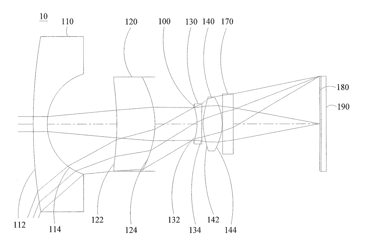
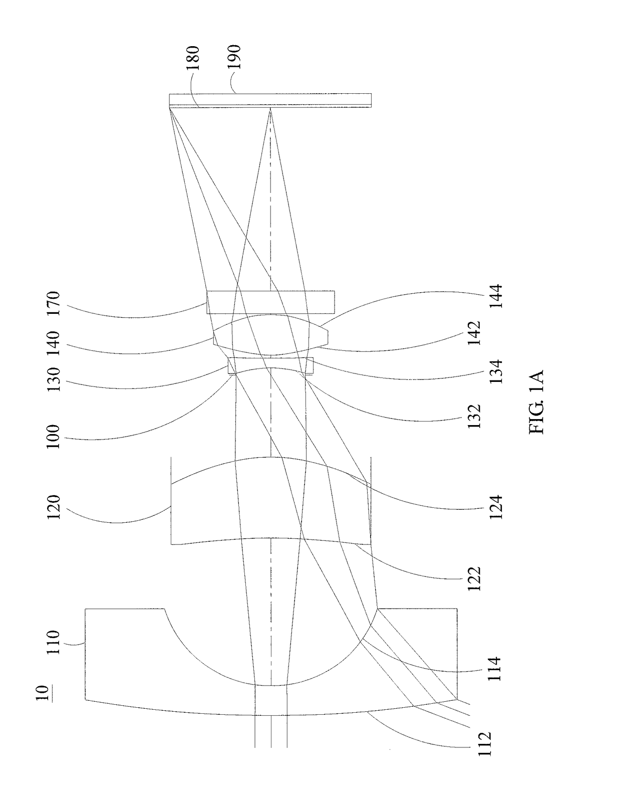
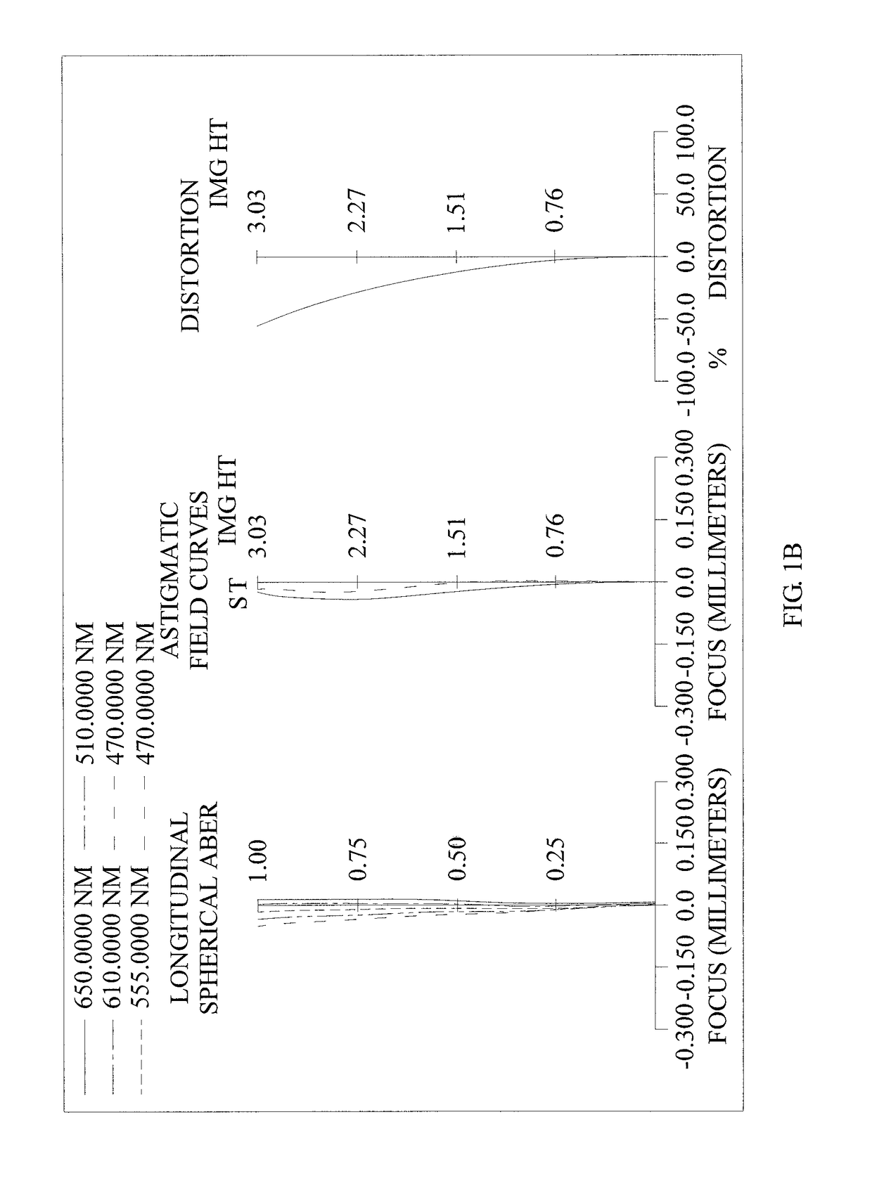
[0124]Please refer to FIGS. 1A to 1E. FIG. 1A is a schematic view of the optical image capturing system according to the first embodiment of the present invention. FIG. 1B shows the longitudinal spherical aberration curves, astigmatic field curves, and optical distortion curve of the optical image capturing system in the order from left to right according to the first embodiment of the present invention. FIG. 1C is a characteristic diagram of modulation transfer of visible light for the optical image capturing system of the first embodiment of the present invention. FIG. 1D is a diagram showing the through-focus MTF values of the visible light spectrum at the central field of view, 0.3 field of view, and 0.7 field of view of the first embodiment of the present invention. FIG. 1E is a diagram showing the through-focus MTF values of the infrared light spectrum at the central field of view, 0.3 field of view, and 0.7 field of view of the first embodiment of the pres...

second embodiment

[0179]Please refer to FIGS. 2A to 2E. FIG. 2A is a schematic view of the optical image capturing system according to the second embodiment of the present invention. FIG. 2B shows the longitudinal spherical aberration curves, astigmatic field curves, and optical distortion curve of the optical image capturing system of the second embodiment, in the order from left to right. FIG. 2C is a characteristic diagram of the modulation transfer of visible light for the optical image capturing system of the second embodiment of the present invention. FIG. 2D is a diagram showing the through-focus MTF values of the visible light spectrum at the central field of view, 0.3 field of view, and 0.7 field of view of the second embodiment of the present invention. FIG. 2E is a diagram showing the through-focus MTF values of the infrared light spectrum at the central field of view, 0.3 field of view, and 0.7 field of view of the second embodiment of the present disclosure. As shown in FIG. 2A, in the o...

third embodiment

[0191]Please refer to FIGS. 3A to 3E. FIG. 3A is a schematic view of the optical image capturing system according to the third embodiment of the present invention. FIG. 3B shows the longitudinal spherical aberration curves, astigmatic field curves, and optical distortion curve of the optical image capturing system, in the order from left to right, according to the third embodiment of the present invention. FIG. 3C is a characteristic diagram of modulation transfer of visible light spectrum for the optical image capturing system according to the third embodiment of the present invention. FIG. 3D is a diagram showing the through-focus MTF values of the visible light spectrum at the central field of view, 0.3 field of view, and 0.7 field of view of the third embodiment of the present invention. FIG. 3E is a diagram showing the through-focus MTF values of the infrared light spectrum at the central field of view, 0.3 field of view, and 0.7 field of view of the third embodiment of the pre...


PUM


Abstract

A four-piece optical lens for capturing image and a five-piece optical module for capturing image are provided. In the order from an object side to an image side, the optical lens along the optical axis includes a first lens with positive refractive power; a second lens with refractive power; a third lens with refractive power; and a fourth lens with refractive power; and at least one of the image-side surface and object-side surface of each of the four lens elements are aspheric. The optical lens can increase aperture value and improve the imagining quality for use in compact cameras.

Description

CROSS-REFERENCE TO RELATED APPLICATION[0001]This application claims priority from Taiwan Patent Application No. 105123105, filed on Jul. 21, 2016, in the Taiwan Intellectual Property Office, the content of which is hereby incorporated by reference in its entirety for all purposes.BACKGROUND OF THE INVENTION1. Field of the Invention[0002]The present disclosure relates to an optical image capturing system, and more particularly to a compact optical image capturing system which can be applied to electronic products.2. Description of the Related Art[0003]In recent years, with the rise of portable electronic devices having camera functionalities, the demand for an optical image capturing system is raised gradually. The image sensing device of ordinary photographing camera is commonly selected from charge coupled device (CCD) or complementary metal-oxide semiconductor sensor (CMOS Sensor). In addition, as advanced semiconductor manufacturing technology enables the minimization of pixel si...

Claims


Application Information

Patent Timeline
Patent Type & Authority Applications(United States)
IPC IPC(8): G02B13/00G02B9/58G02B7/04G02B27/64G02B13/14G02B9/34
CPCG02B13/008G02B13/146G02B9/34G02B5/20G02B13/004G02B27/646G02B9/58G02B7/04
Inventor LAI, CHIEN-HSUNLIAO, KUO-YULIU, YAO-WEICHANG, YEONG-MING
Owner ABILITY OPTO ELECTRONICS TECH
Why Eureka
Try Eureka