Power transmission line fault accessibility discrimination method based on image features

A technology of transmission lines and image features, applied in the fault location, detecting faults according to conductor types, etc., can solve the problems of wrong ranging results, misoperation, affecting the reliability of the traveling wave method, etc., to avoid misoperation and misdetection, Improve the effect of the application

Pending Publication Date: 2022-03-15
KUNMING UNIV OF SCI & TECH
View PDF0 Cites 0 Cited by
  • Summary
  • Abstract
  • Description
  • Claims
  • Application Information

AI Technical Summary

Problems solved by technology

[0003] In the absence of initial traveling waves or only interference, traveling wave protection and ranging devices may produce erroneous results, or lead to misoperation or wrong ranging results, affecting the reliability of the traveling wave method as an independent decision

Method used


Image

  • Power transmission line fault accessibility discrimination method based on image features
  • Power transmission line fault accessibility discrimination method based on image features
  • Power transmission line fault accessibility discrimination method based on image features

Examples


Embodiment 1

[0041] Example 1, such as Figure 11 As shown, a fault persistence discrimination method based on image features, the specific steps are as follows:

[0042] Step1: Collect fault traveling wave data at the end of the transmission line and select a data window based on straight line calibration to ensure that the window can observe the process of traveling wave mutation.

[0043] Step2: Display the data window in the image, and construct a triangular bounding box that has a good and close relationship with the region of interest.

[0044] Such as Figure 7 As shown, when the mutation process of the initial wave head can be reflected in the triangular bounding box, that is, its range is covered by the triangular bounding box, the relationship is defined as good and close.

[0045] Step3: Calculate the ratio of the continuation area formed by the fault traveling wave and the outer tangent in the bounding box to the entire bounding box, and judge whether the initial wave head of...

Embodiment 2

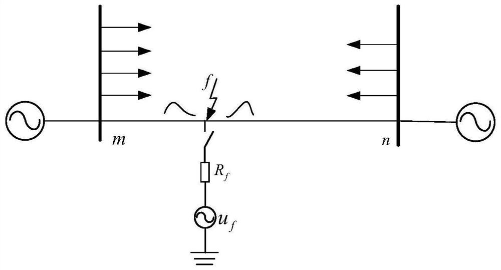
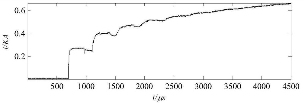
[0078] Embodiment 2: as figure 1 As shown, based on PSCAD / EMTDC build as figure 1 In the 220kV transmission line model shown, the total length of the fault line is 100km, and a phase A ground fault occurs at a distance of 60km from the observation point, where the fault angle is 30°, the transition resistance is 50Ω, and the sampling rate is 1MHz. 10% noise is added to the fault current simulation data, and its waveform is as follows figure 2 shown. The specific implementation steps are:

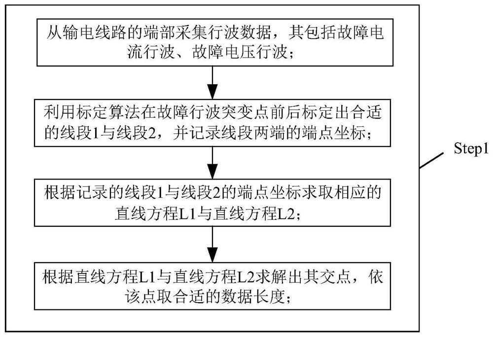
[0079] Step1: Collect the fault current data at the end of the transmission line and select the appropriate data window based on the linear calibration. The specific implementation steps are as follows image 3 shown.

[0080] Step1.1: Collect fault current traveling wave data from the M end of the transmission line.

[0081] Step1.2: Use the calibration algorithm to calibrate the appropriate line segment 1 and line segment 2 before and after the fault traveling wave mutation point, an...


PUM


Abstract

The invention relates to a power transmission line fault continuity judgment method based on image features, and belongs to the technical field of power system protection. Fault traveling wave data at the end of a power transmission line are collected, and a proper data window is selected based on linear calibration; displaying a proper data window in the image, and constructing a triangular bounding box which is well close to the region of interest; calculating the ratio of the continuation area formed by the fault traveling wave and the external tangent line in the bounding box to the whole bounding box, and judging whether a fault initial wave head exists or not according to the ratio; on the basis of existence of a fault initial wave head, regularization of initial and subsequent wave heads is carried out, relative characteristics of an arrival time sequence, a wave head amplitude and a slope are calculated based on the regularized calibration wave head, and finally fault continuity discrimination is realized. According to the method, the fault data without the traveling wave head can be automatically screened out, and the line fault traveling wave accessibility can be judged.

Description

technical field [0001] The invention relates to a method for judging the persistence of faults of power transmission lines based on image features and belongs to the technical field of electric power system protection. Background technique [0002] After the transmission line is faulty, it is necessary to realize the removal of the faulty line and the accurate judgment of the fault location in a short time to ensure the safe and reliable operation of the power system. significance. Traveling wave has the advantages of fast response speed, not affected by the type of line and the system on both sides, etc. It has natural advantages in rapid protection and accuracy of line positioning. It is particularly important to fully explore the advantages of traveling wave and apply it to the engineering site Urgent and necessary. [0003] In the case of no initial traveling wave or only interference, the traveling wave protection and ranging device may produce wrong results, or lead ...

Claims


Application Information

Patent Timeline
Patent Type & Authority Applications(China)
IPC IPC(8): G01R31/08
CPCG01R31/085
Inventor 张广斌黄杨王潜束洪春
Owner KUNMING UNIV OF SCI & TECH
Why Eureka
Try Eureka