Brake assembly, electric tool switch and electric tool

A technology of brake components and electric tools, applied in the field of brake components, can solve problems such as low brake life, and achieve the effects of improving brake life, prolonging service life and long service life

Pending Publication Date: 2022-03-15
SHANGHAI BAICHENG ELECTRONICS
View PDF0 Cites 0 Cited by
  • Summary
  • Abstract
  • Description
  • Claims
  • Application Information

AI Technical Summary

Problems solved by technology

[0005] Another object of the present invention is to propose an electric tool switch to overcome the technical problem of low brake life in traditional electric tool switches

Method used


Image

  • Brake assembly, electric tool switch and electric tool
  • Brake assembly, electric tool switch and electric tool
  • Brake assembly, electric tool switch and electric tool

Examples


Embodiment Construction

[0032] The technical solutions of the present invention will be further described below in conjunction with the accompanying drawings and through specific implementation methods.

[0033] In describing the present invention, it is to be understood that the terms "upper", "lower", "front", "rear", "left", "right", "vertical", "horizontal", "top", The orientation or positional relationship indicated by "bottom", "inner", "outer", etc. is based on the orientation or positional relationship shown in the drawings, and is only for the convenience of describing the present invention and simplifying the description, rather than indicating or implying the referred device Or elements must have a certain orientation, be constructed and operate in a certain orientation, and thus should not be construed as limiting the invention.

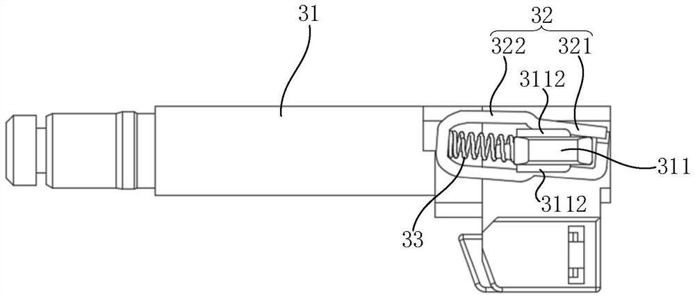
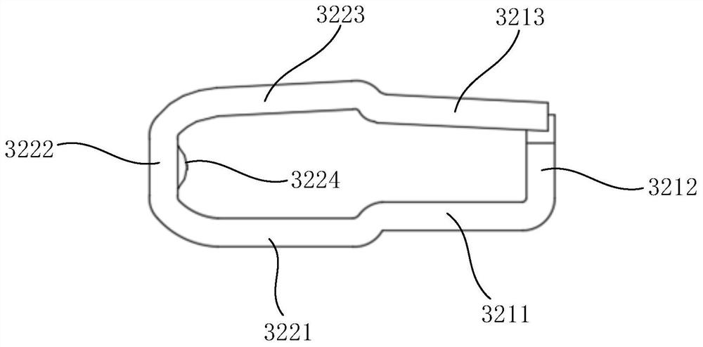
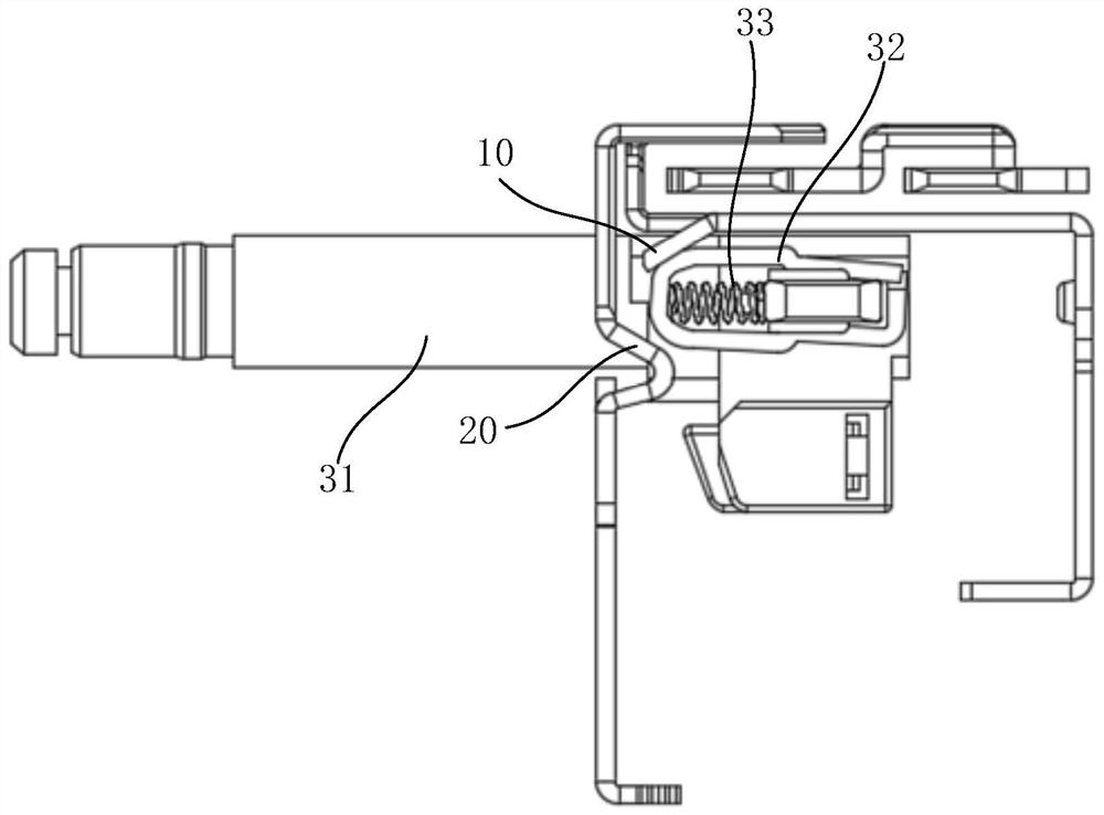
[0034] Please also see Figure 1 to Figure 4 , the present embodiment provides a brake assembly, the brake assembly is partly arranged in the electric tool swi...


PUM


Abstract

The invention discloses a brake assembly, an electric tool switch and an electric tool, the brake assembly is partially arranged in the electric tool switch, is used for short circuit of a terminal D connected with a motor and a main loop terminal in the electric tool switch, and comprises a push rod, a brake pad and a brake spring, the brake pad is installed on the push rod, and the brake spring is installed on the brake pad. The brake spring is arranged between the brake pad and the push rod, the brake pad comprises a short circuit part, the brake pad has an initial state and a brake state, and when the brake pad is in the initial state, the short circuit part is obliquely arranged towards the side close to the D terminal; when the brake pad is in a braking state, the short circuit part and the push rod are arranged in parallel, and the short circuit part abuts against the D terminal and the main loop terminal. The brake assembly can prolong the brake service life of the electric tool switch and prolong the service life of the electric tool. Correspondingly, the invention further provides an electric tool switch and an electric tool.

Description

technical field [0001] The invention relates to the field of electric tools, in particular to a brake assembly, an electric tool switch and an electric tool. Background technique [0002] In order to ensure the safety of the electric tool, when the electric tool switch is disconnected, the electric tool is required to stop immediately with the disconnection of the tool switch, so as to prevent the motor of the electric tool from continuing to work under the action of inertia after the electric tool is disconnected, causing harm to the human body. Therefore, general electric drills, electric wrenches, electric saws, electric hammers and other electric tools will require the electric tool switch to have a brake function. When the whole machine needs to stop immediately, the switch brake will stop the electric tool immediately. [0003] The braking method of existing electric tools is that when the switch of the electric tool returns from the working position to the braking pos...

Claims


Application Information

Patent Timeline
Patent Type & Authority Applications(China)
IPC IPC(8): H01H9/02H01H9/20B25F5/00
CPCH01H9/02H01H9/20B25F5/00
Inventor 王金峰丁峰
Owner SHANGHAI BAICHENG ELECTRONICS
Why Eureka
Try Eureka