
Device for reducing low-light jitter of light source by using vibration suppression module and lamp

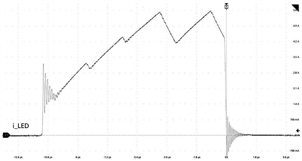
A low-brightness, light source technology, applied in the field of semiconductor lighting equipment, can solve problems such as inability to eliminate, time-consuming and labor-intensive effects, poor effects, etc., to achieve the effect of eliminating current ripple, suppressing current oscillation, and avoiding light flickering

Pending Publication Date: 2022-03-15
GUANGZHOU HAOYANG ELECTRONICS CO LTD
View PDF0 Cites 0 Cited by
  • Summary
  • Abstract
  • Description
  • Claims
  • Application Information

AI Technical Summary

Problems solved by technology

This manual trial and error operation is time-consuming and laborious, and the effect is not good
At the same time, the current ripple of the circuit can only be reduced, but cannot be eliminated. However, even if the current ripple is adjusted to a small value, it will be exposed to the dimming process

Method used


Image

  • Device for reducing low-light jitter of light source by using vibration suppression module and lamp
  • Device for reducing low-light jitter of light source by using vibration suppression module and lamp
  • Device for reducing low-light jitter of light source by using vibration suppression module and lamp

Examples


Embodiment 1

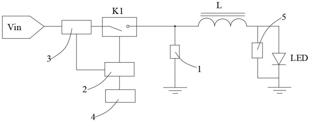
[0057] Such as figure 2 As shown, this embodiment provides a device for reducing low-brightness jitter of a light source by using a vibration suppression module.

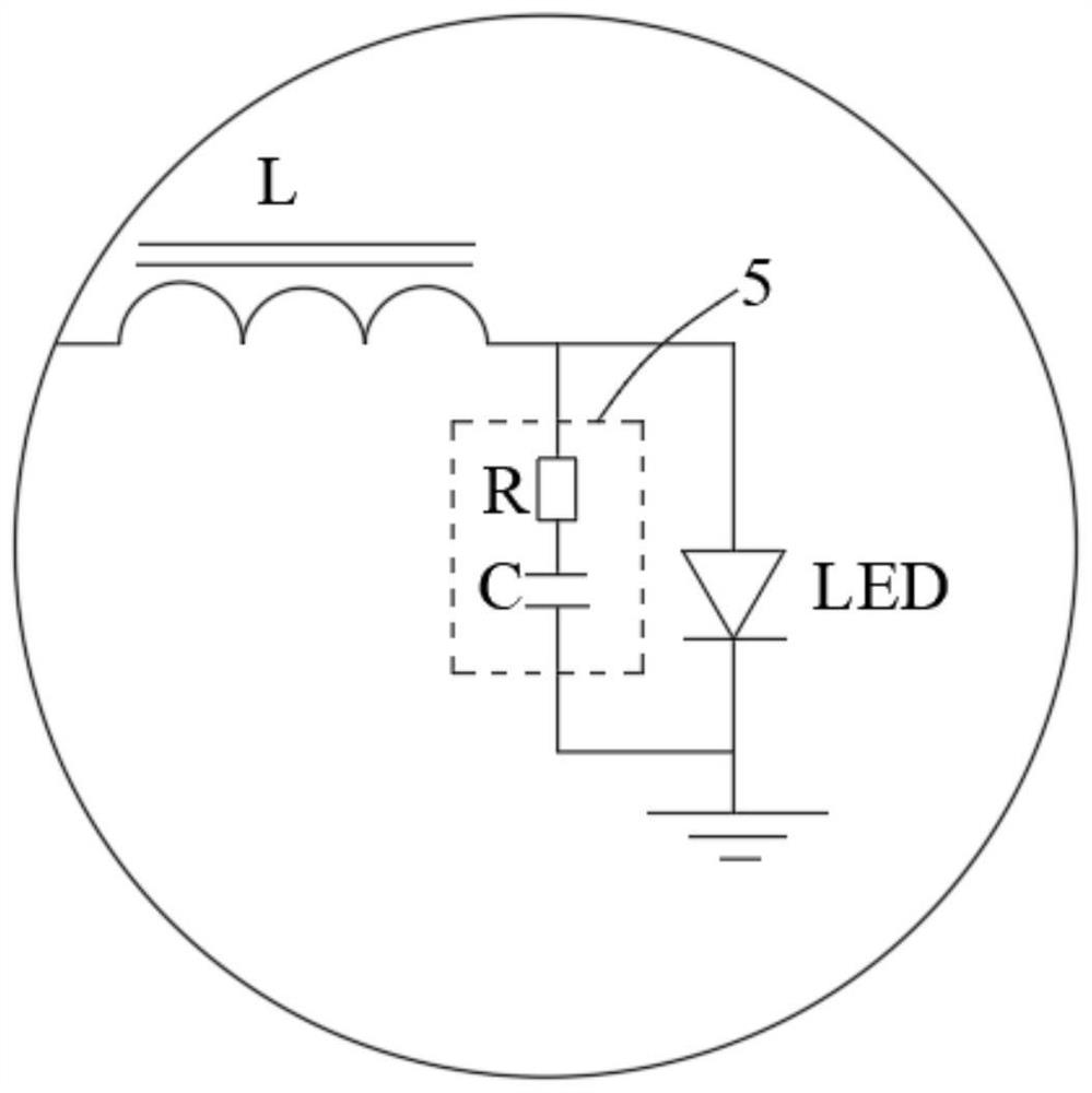
[0058] Including: LED light source, inductor L, current control module 1, switch K1, signal control module 2, current acquisition module 3 and vibration suppression module 5;

[0059] The first terminal of switch K1 is used for the input voltage V in , the second end of the switch K1 is connected to the first end of the inductor L;

[0060] The second end of the inductor L is connected to the anode of the LED light source, and the cathode of the LED light source is grounded;

[0061] The first end of the current control module 1 is connected to the second end of the switch K1 and the first end of the inductor L, and the second end of the current control module 1 is grounded. When the switch K1 is closed, the current control module 1 is turned off, and when the switch K1 is turned off When on, the current control...

Embodiment 2

[0144]Based on the device provided in Embodiment 1 to reduce low-brightness jitter of a light source by using a vibration suppression module, this embodiment provides a method for reducing low-brightness jitter of a light source by using a vibration suppression module, which is used to control a device in Embodiment 1 that utilizes a suppression The vibration module reduces the current change rate of the LED light source in the device for reducing the low-brightness jitter of the light source, including the following steps:

[0145] The current change rate k of the current flowing through the LED light source is reduced so that the current flowing through the LED light source does not generate current ripples in the dark area.

[0146] When the switch K1 is closed, the current flows to the LED light source, so that the current on the LED light source increases gradually, and the LED light source gradually becomes brighter. However, if the current on the LED light source rises ...

Embodiment 3

[0181] This embodiment provides a lamp, including one or more devices for reducing low-brightness jitter of a light source by using a vibration suppression module as in Embodiment 1.


PUM

PropertyMeasurementUnit
Resonant frequencyaaaaaaaaaa

Abstract

The invention relates to the field of semiconductor lighting equipment, in particular to a device for reducing low-light jitter of a light source through a vibration suppression module and a lamp. The invention discloses a device for reducing low-brightness jitter of a light source by using a vibration suppression module. The device comprises an LED light source, an inductor L, a current control module, a switch K1, a signal control module, a current acquisition module and the vibration suppression module. According to the technical scheme, current ripples of the current in the LED light source in the rising process can be eliminated, current oscillation generated when the current suddenly changes can be restrained, the current on the LED light source can stably rise, the LED light source can stably brighten in the dark portion dimming process, and the phenomena of lamplight flickering and jittering caused by the current oscillation and the current ripples are avoided.

Description

technical field [0001] The invention relates to the field of semiconductor lighting equipment, and more specifically, to a device and a lamp that use a vibration suppression module to reduce low-brightness jitter of a light source. Background technique [0002] The human eye is sensitive to changes in light in a dark environment. For example, we can see the faint changes in the fluorescent flickering of fireflies in the dark. However, the human eye is numb to the perception of light changes in a strong light environment. For example, in the hot sun, there is no difference between the lumens of 1 candle and 2 candles. [0003] In the prior art, there must be parasitic inductance in the wires in the circuit board, and there must be parasitic capacitance in the components. These parasitic parameters will more or less generate current oscillation under the action of the sudden change of current. Even if the current oscillation is small, it will still be exposed to the above usa...

Claims


Application Information

Patent Timeline
Patent Type & Authority Applications(China)
IPC IPC(8): H05B45/10H05B45/14H05B45/36H05B45/325H05B45/59H05B45/50
CPCH05B45/10H05B45/14H05B45/36H05B45/325H05B45/59H05B45/50H05B45/3725Y02B20/30
Inventor 蒋伟楷其他发明人请求不公开姓名
Owner GUANGZHOU HAOYANG ELECTRONICS CO LTD
Learn More