Butt joint structure with replaceable assembly and continuous clip applier for surgical robot

The technology of a clip applier and a docking mechanism is applied in the field of continuous hair clip appliers for surgical robots, which can solve the problems of high cost, contamination of the actuator of the surgical robot, inconvenient addition of tissue clips, etc., and achieves easy adjustment and convenient organization. The number and type of clips, the effect of improving the convenience of use

Pending Publication Date: 2022-03-18
苏州威森特医疗机器人有限公司 +1
View PDF0 Cites 0 Cited by
  • Summary
  • Abstract
  • Description
  • Claims
  • Application Information

AI Technical Summary

Problems solved by technology

[0003] In the same surgery, in order to meet the above requirements, if the overall disassembly and replacement of the clip applier is used to adjust the type of tissue clips and add tissue clips, it is not convenient and the cost is high. At the same time, repeated operations will easily increase the contamination of the actuator of the surgical robot. risk

Method used


Image

  • Butt joint structure with replaceable assembly and continuous clip applier for surgical robot
  • Butt joint structure with replaceable assembly and continuous clip applier for surgical robot
  • Butt joint structure with replaceable assembly and continuous clip applier for surgical robot

Examples


Embodiment 1

[0055] Such as Figures 1 to 8 shown, refer to the attached Figures 9 to 19 , the docking structure of the replaceable components is disclosed in this embodiment. It includes a first docking mechanism and a second docking structure, and the first docking mechanism and the second docking structure are respectively fixedly connected with the two ends that need to be docked in the process of replacing components.

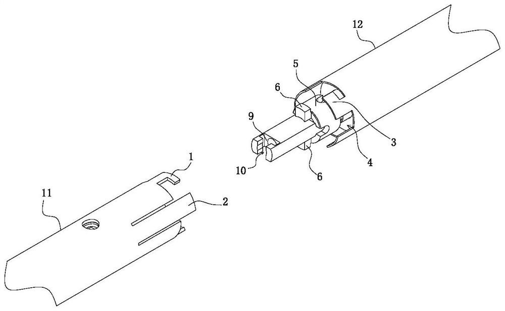
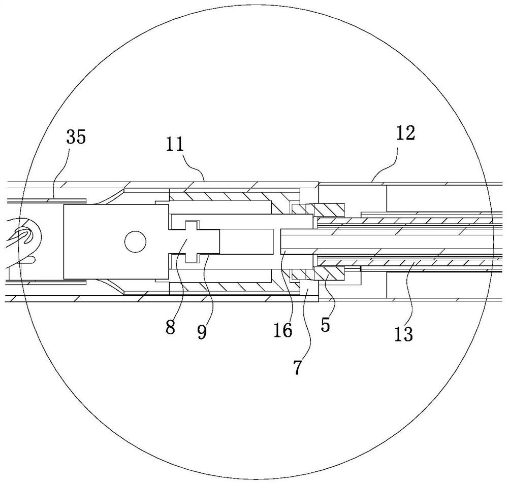
[0056] Such as figure 2 As shown, the first docking mechanism includes a first hook 1 and an anti-rotation shrapnel 2 . The second docking mechanism includes a second hook 3 and an anti-rotation groove 4 . Such as Figure 6 As shown, when the two ends are butted, the first hook 1 is hooked with the second hook 3 , and the anti-rotation shrapnel 2 is fitted into the anti-rotation groove 4 .

[0057] Refer to attached figure 2 and 6 , during the butt joint process of the two ends, the first hook reaches the hooking position of the second hook from the channel, ...

Embodiment 2

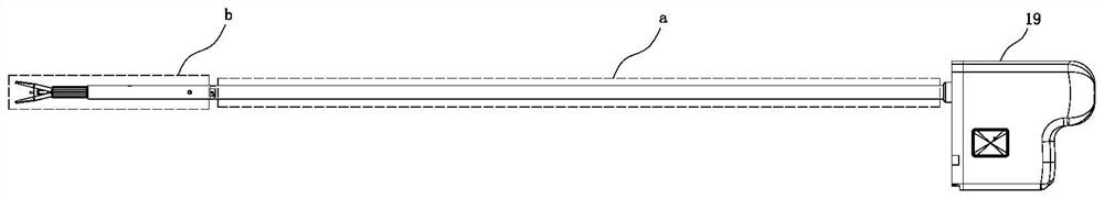
[0067] Such as Figures 9 to 19 As shown, with reference to other drawings in the accompanying drawings, the front part of the shaft part a of the continuous clamp applicator for the robot disclosed in this embodiment is docked with a replaceable component b, and the docking structure adopted is the one used in Embodiment 1. Open docking structure.

[0068] The continuous clip applier for surgical robots disclosed in this embodiment includes a replaceable component b located at the front of the clip applier, and the replaceable component b and the shaft part a of the clip applier pass through the replaceable component b. The docking structure is connected.

[0069] In this embodiment, the two ends that need to be butted in the process of replacing the components described in Embodiment 1 are the front end of the shaft portion a of the clamp applier and the rear end of the replaceable component b respectively.

[0070] Refer to attached Figure 6 , the first docking mechanis...

Embodiment 3

[0101] This embodiment is further optimized on the basis of embodiment 2:

[0102] Refer to attached Figures 1 to 19 ,Such as Figure 14 As shown, the body base 19 includes a base 51, a middle bracket 52 and a top bracket 53, the middle bracket 52 and the top bracket 53 are fixedly connected with the base 51 respectively, and the top of the first columnar body 25 is rotatable with the top bracket 53. Connected, the bottom of the second columnar body 26 is rotatably connected with the middle bracket 52; the third columnar body 24 of the continuous clip applier pliers is rotatably connected with the base 51. In this embodiment, the structures that are rotatably connected to each other are connected by bearings. The first chuck 20, the second chuck 22 and the third chuck 46 of the body base 19 stretch out to the outside of the base 51 respectively, and the first chuck 20, the second chuck 22, the third chuck 46 are respectively connected with A plurality of brake discs or act...


PUM


Abstract

On one hand, the butt joint structure capable of replacing the assembly comprises a first butt joint mechanism and a second butt joint structure, and the first butt joint mechanism and the second butt joint structure are fixedly connected with the two ends needing to be in butt joint in the assembly replacing process correspondingly; the first butt joint mechanism comprises a first hook and a rotation stopping elastic piece. The second butt joint mechanism comprises a second hook and a rotation stopping groove. When the two end portions are in butt joint, the first hook is hooked with the second hook, and the rotation stopping elastic piece is embedded into the rotation stopping groove. The invention further discloses the continuous clip applier for the surgical robot, the continuous clip applier comprises the replaceable assembly located on the front portion of the clip applier, and the replaceable assembly is connected with the shaft rod portion of the clip applier through the butt joint structure of the replaceable assembly. The shaft rod part of the clip applier can be in detachable butt joint with the replacement assembly, the number, model and the like of the tissue clips can be adjusted conveniently, and use convenience is improved. The number and model of the tissue clips are convenient to adjust, and use cost is reduced.

Description

technical field [0001] The invention belongs to the technical field of manipulators on the patient side in a surgical robot system, and in particular relates to a docking structure of replaceable components and a continuous clip applier for a surgical robot. Background technique [0002] A clip applier is a surgical instrument used to close plastic or metal clips on blood vessels or urinary tubes. During minimally invasive surgery, the clip applier is directly actuated by the surgical robot, and the clip applier is connected to the actuation disk / actuation motor of the surgical robot during use. In some minimally invasive surgery plans, there will be a need to change the size of the tissue clips and temporarily increase the number of tissue clips. [0003] In the same operation, in order to meet the above requirements, if the overall disassembly and replacement of the clip applier is used to adjust the type of tissue clip and add tissue clips, it is not convenient and the c...

Claims


Application Information

Patent Timeline
Patent Type & Authority Applications(China)
IPC IPC(8): A61B17/128A61B34/30
CPCA61B17/1285A61B34/30A61B2034/302
Inventor 庞建高轶明翟俊旺
Owner 苏州威森特医疗机器人有限公司
Why Eureka
Try Eureka