
Glue spraying gun special for gluing

A glue gun and glue gun technology, applied in the field of glue gun, can solve the problems of high cost and price, different structures, inconvenient use, etc., and achieve the effects of reducing labor costs, ensuring life, and reducing shaking

Inactive Publication Date: 2022-03-18
国翌智能科技(上海)有限公司
View PDF0 Cites 1 Cited by
  • Summary
  • Abstract
  • Description
  • Claims
  • Application Information

AI Technical Summary

Problems solved by technology

[0002] When applying glue to different parts such as the bottom of the car and the interior of the car, it is necessary to use a glue gun for processing. The existing glue guns have different structures, and the cost is relatively high. It is extremely inconvenient to use.

Method used


Image

  • Glue spraying gun special for gluing
  • Glue spraying gun special for gluing
  • Glue spraying gun special for gluing

Examples


Embodiment 1

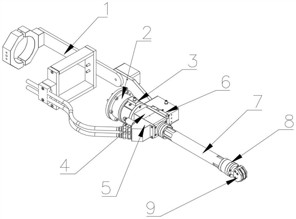
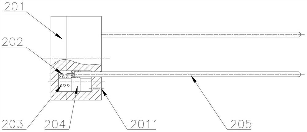
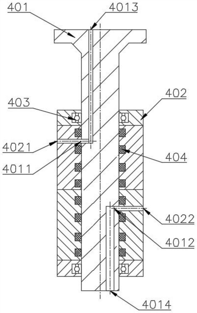
[0024] Example 1: See Figure 1-3 , the present invention provides a technical solution: a special spray gun for gluing, including a glue gun connecting bracket 1, a control valve group unit 2, a slip ring unit 3, a glue gun rotation unit 4, a glue supply unit 5, and a solenoid valve group Unit 6, glue gun connecting pipe unit 7, valve seat unit 8 and nozzle unit 9, control valve group unit 2 is arranged on the glue gun connecting bracket 1, glue gun rotating unit 4 includes rotating mandrel 401 and rotating chamber 402, and rotates The mandrel 401 is set through the rotating chamber 402, the rotating mandrel 401 is connected with the control valve group unit 2, the rotating chamber 402 is connected with the glue gun connecting bracket 1, the slip ring unit 3 is connected with the glue gun rotating unit 4, and is used to control the valve The sensor wiring of the group unit 2, the two sides of the control valve group unit 2 are respectively fixedly connected with the glue supp...

Embodiment 2

[0031] Example 2: See Figure 4-6 , the present invention provides a technical solution: a special spray gun for gluing, including a glue gun connection bracket 1, a glue gun rotation unit 4, a glue supply unit 5, a solenoid valve group unit 6, a glue gun connection pipe unit 7, an integrated Type cut-off valve group unit 10 and glue gun nozzle unit 9, glue gun rotating unit 4 is connected with glue gun connecting bracket 1, glue gun rotating unit 4 includes rotating mandrel 401 and rotating chamber 402, rotating mandrel 401 is arranged on rotating chamber In 402, the rotating cavity 402 is connected with the glue gun connection bracket 1, the glue supply unit 5 and the solenoid valve group unit 6 are respectively fixedly connected to both sides of the glue gun rotation unit 4, and the glue supply unit 5 is provided with a glue inlet port and Glue outlet interface, one end of the glue gun connecting pipe unit 7 is connected to the rotating mandrel 401 of the glue gun rotating ...


PUM


Abstract

The invention relates to the technical field of glue spraying guns, and particularly discloses a special glue spraying gun for gluing, which comprises a glue gun connecting bracket, a control valve group unit, a slip ring unit, a glue gun rotating unit, a glue supply unit, an electromagnetic valve group unit, a glue gun connecting pipe unit, a valve seat unit and a nozzle unit, the glue gun rotating unit comprises a rotating mandrel and a rotating cavity, the rotating mandrel penetrates through the rotating cavity and is connected with the control valve set unit, the rotating cavity is connected with the glue gun connecting support, and the sliding ring unit is connected with the glue gun rotating unit. The two sides of the control valve set unit are fixedly connected with the glue supply unit and the electromagnetic valve set unit respectively, the glue supply unit is provided with a glue inlet connector and a glue outlet connector, the glue gun connecting support is connected with the robot, the glue gun moves along with the robot and is driven by a main shaft of the robot to rotate, and the gluing function at different positions of an automobile is achieved.

Description

technical field [0001] The invention relates to the technical field of glue spray guns, in particular to a special glue spray gun for glue application. Background technique [0002] When applying glue to different parts of the car bottom and inside the car, it is necessary to use a glue gun for processing. The existing glue guns have different structures, and the cost is relatively high, which is extremely inconvenient to use. Contents of the invention [0003] The object of the present invention is to provide a special glue spray gun for glue application, so as to solve the problems raised in the above-mentioned background technology. [0004] In order to achieve the above object, the present invention provides the following technical solutions: a special spray gun for gluing, including a glue gun connection bracket, a control valve group unit, a slip ring unit, a glue gun rotation unit, a glue supply unit, a solenoid valve group unit, A glue gun connecting pipe unit, a ...

Claims


Application Information

Patent Timeline
Patent Type & Authority Applications(China)
IPC IPC(8): B05C5/02B05C11/10B25J11/00
CPCB05C5/0225B05C11/1026B05C11/1044B05C11/1039B25J11/0075
Inventor 张锐周军李瑞
Owner 国翌智能科技(上海)有限公司
Learn More