Reverse backfill type friction stir spot welding method

A friction stir and spot welding technology, used in welding equipment, non-electric welding equipment, metal processing equipment, etc., can solve the problems of increasing grain size, reducing material fluidity, and difficulty in material backfilling, reducing interface distortion and reducing Macroscopic deformation, beneficial effect of metallurgical bonding effect

Pending Publication Date: 2022-03-18
SHENYANG AEROSPACE UNIVERSITY
View PDF9 Cites 0 Cited by
  • Summary
  • Abstract
  • Description
  • Claims
  • Application Information

AI Technical Summary

Problems solved by technology

However, the invention does not consider the fluidity of materials at different rotational speeds when adjusting the synchronous rotational speed. The high heat generated during the synchronous high rotational speed stage will enhance the fluidity of the material, but the high heat will also cause problems such as increased grain size in the heat-affected zone; Although the adverse effect of high heat is reduced in the stage

Method used


Image

  • Reverse backfill type friction stir spot welding method
  • Reverse backfill type friction stir spot welding method
  • Reverse backfill type friction stir spot welding method

Examples


Example Embodiment

[0061] Example 1

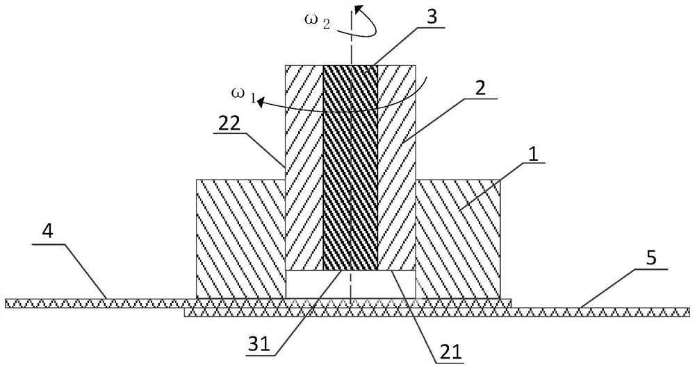
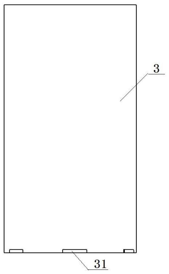
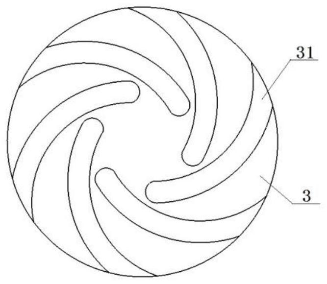
[0062] A reverse backfiltered stirring friction spot welding method is carried out with a reverse backfiltered stirred friction spot welding tool, and the reverse backfilling is mixed by the compression ring 1, the sleeve 2 and the stirring needle 3 in the coaxial. The welding process includes four stages of preheating, lowering, backfilling, and evacuation: reverse backfilling stitling friction spot welding method, reverse backfilling, friction spot welding tool and soldered sheet, cross section structure figure 1 As shown, the front view of the mixing needle 3 is figure 2 As shown, look up image 3 Down; the front view of the sleeve 2 is Figure 4 As shown, look up Figure 5 As shown; the spot welding object is the upper soldered sheet 4, and the lower side is soldered sheet 5. The sleeve 2 has a spiral pass groove 21 on the end surface, and the outer side surface has a large heaven groove 22. The large-scale trough is 30 °, the spacing is 2.5mm, the spiral width...

Example Embodiment

[0074] Example 2

[0075] A reverse backfiltered stirring friction spot welding method is carried out with a reverse backfiltered stirred friction spot welding tool, and the reverse backfilling is mixed by the compression ring 1, the sleeve 2 and the stirring needle 3 in the coaxial. The welding process includes four stages of preheating, lowering, backfilling, and evacuation: reverse backfilling stitling friction spot welding method, reverse backfilling, friction spot welding tool and soldered sheet, cross section structure figure 1 As shown, the front view of the mixing needle 3 is figure 2 As shown, look up image 3 Down; the front view of the sleeve 2 is Figure 4 As shown, look up Figure 5 As shown; the spot welding object is the upper soldered sheet 4, and the lower side is soldered sheet 5. The sleeve 2 has a spiral pass groove 21 on the end surface, and the outer side surface has a large heaven groove 22. The large-scale trough is 30 °, the spacing is 2.5mm, the spiral width...

Example Embodiment

[0083] Example 3

[0084] A reverse backfiltered stirring friction spot welding method is carried out with a reverse backfiltered stirred friction spot welding tool, and the reverse backfilling is mixed by the compression ring 1, the sleeve 2 and the stirring needle 3 in the coaxial. The welding process includes four stages of preheating, lowering, backfilling, and evacuation: reverse backfilling stitling friction spot welding method, reverse backfilling, friction spot welding tool and soldered sheet, cross section structure figure 1 As shown, the front view of the mixing needle 3 is figure 2 As shown, look up image 3 Down; the front view of the sleeve 2 is Figure 4 As shown, look up Figure 5 As shown; the spot welding object is the upper soldered sheet 4, and the lower side is soldered sheet 5. The sleeve 2 has a spiral pass groove 21 on the end surface, and the outer side surface has a large heaven groove 22. The large-scale trough is 30 °, the spacing is 2.5mm, the spiral width...


PUM

PropertyMeasurementUnit
Tensile strengthaaaaaaaaaa

Abstract

The invention discloses a reverse backfill type friction stir spot welding method, and belongs to the technical field of welding. A reverse backfill type friction stir spot welding tool is adopted, the end faces of a stirring needle, a sleeve and a pressing ring are located on the same horizontal plane and integrally pressed down to the upper surface of a welded plate, a welded workpiece is pressed, the stirring needle and the sleeve are rotated, the rotating speed of the sleeve is omega1, the rotating speed of the stirring needle is omega2, reverse rotation is conducted, omega1 is smaller than omega2, and the surface of the welded workpiece is preheated. The sleeve rotates to downwards pierce into the welded plate on the upper side, meanwhile, the stirring needle reversely rotates to upwards draw back until the sleeve rotates to pierce into the surface of the welded plate on the lower side, and metal is squeezed into a cavity of the sleeve; the sleeve and the stirring needle change directions simultaneously, and plastic metal in a cavity of the sleeve is backfilled to the upper surface of the welded plate on the upper side; and the two return to the upper surface of the welded plate on the upper side and stop rotating, welding is completed, and a weldment is obtained. According to the method, heat input in the welding process is greatly reduced, interface metallurgical bonding of a stirring area and a heat engine influence area is improved, and meanwhile residual stress and deformation after test plate welding are reduced.

Description

Technical field [0001] The present invention belongs to the field of technology welding, and more particularly to a reverse backfiltered stirring friction spot welding method. Background technique [0002] Refilled Franch Stir Spot Welding, RfSSW) Due to the advantages of high-quality, high strength, the strength of the welding point is high in the welding process, the structure of light alloy is used in aerospace, ship, orbit train and automotive industry. The field has great application prospects. During the filling of the backfill, the thermal influence of the high temperature cycle is roughened into one of the weak links of the solder joint, and the degree of crystal grains increases with the increase in welding temperature, resulting in mechanical properties of the material. Reduce, thereby directly affecting the quality of the welded joint. Scholars have proposed improvements and measures for improving the strength of the blend of filling friction sites. [0003] In the pri...

Claims


Application Information

Patent Timeline
IPC IPC(8): B23K20/12B23K20/26
CPCB23K20/1255B23K20/26Y02P70/10
Inventor 姬书得杨康马琳张芷晴孟庆实熊需海胡为宋崎龚鹏
Owner SHENYANG AEROSPACE UNIVERSITY
Why Eureka
Try Eureka