Adjusting type flatness detection device for electromechanical component
A detection device and an adjustable technology, applied in the field of adjustable flatness detection devices, can solve the problems of inconvenient flatness detection of different types of planes and the like
- Summary
- Abstract
- Description
- Claims
- Application Information
AI Technical Summary
Problems solved by technology
Method used
Image
Examples
Embodiment 1
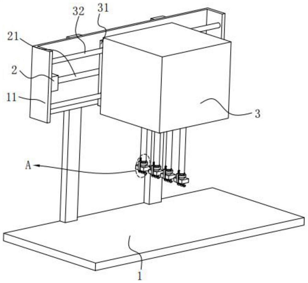
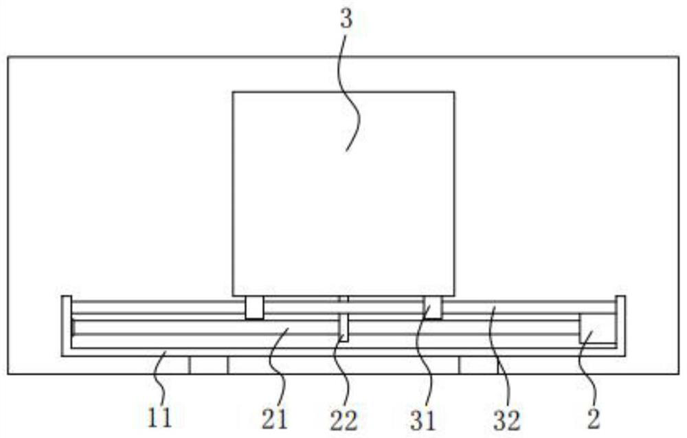
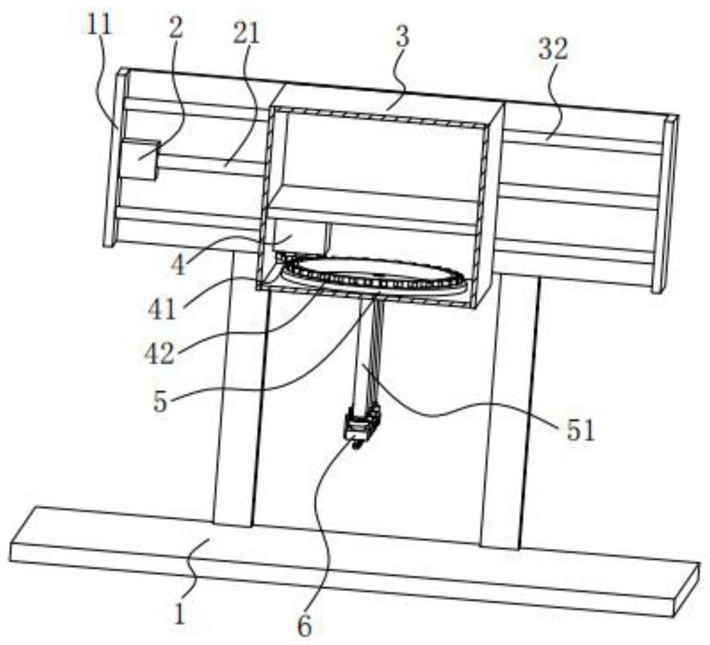
[0037] An adjustable flatness detection device for electromechanical components includes: a detection table 1, a mounting frame 11 is installed on the top of the detection table 1; a travel motor 2, and the travel motor 2 is installed on the inside of the mounting frame 11 , the output end of the walking motor 2 is fixedly equipped with a screw mandrel 21, and the surface of the screw mandrel 21 is threadedly connected with a linkage plate 22; a detection chassis 3, and the detection chassis 3 is installed on the surface of the linkage plate 22; Motor 4, the surface of the rotating motor 4 is installed on the inner wall of the detection cabinet 3, the output end of the rotating motor 4 is fixedly installed with a driving gear 41, and the surface of the driving gear 41 is threadedly connected with a driven gear ring 42; The turret 5, the surface of the turret 5 is rotatably mounted on the bottom of the detection cabinet 3, and the bottom end of the turret 5 is fixedly equipped w...
Embodiment 2
[0055] Preferably, the top of the detection frame 6 is rotatably mounted on the bottom end of the connecting sleeve 51, the outer surface of the detection frame 6 is fixedly connected with a movable sleeve rod 7, and the top of the movable sleeve rod 7 is fixedly connected with a A positioning spring 71, on which a positioning pin 72 is mounted, a positioning disk 8 is fixedly mounted on the outer surface of the connecting sleeve 51, and a positioning hole 81 is opened on the positioning disk 8.
[0056] The detection frame 6 is mounted on the bottom of the connecting sleeve 51 in a movable manner, so as to adjust the use state of the detection probe 61 at the bottom of the detection frame 6 and provide two detection methods with different detection functions. The positioning pin shaft 72 is lifted up, so that the positioning pin shaft 72 is separated from the inside of one positioning hole 81, the detection frame 6 is rotated, and the positioning pin shaft 72 is rotated to the...
PUM
 Abstract
Description
Claims
Application Information
 - R&D
- Intellectual Property
- Life Sciences
- Materials
- Tech Scout
- Unparalleled Data Quality
- Higher Quality Content
- 60% Fewer Hallucinations
Browse by: Latest US Patents, China's latest patents, Technical Efficacy Thesaurus, Application Domain, Technology Topic, Popular Technical Reports.
© 2025 PatSnap. All rights reserved.Legal|Privacy policy|Modern Slavery Act Transparency Statement|Sitemap|About US| Contact US: help@patsnap.com


