Non-standard buoyancy lift pin machining inspection equipment with directional trimming detection function

A technology of inspection equipment and floating pins, applied in the field of floating pins, can solve problems such as reduced production efficiency and no detection, and achieve the effect of reducing personnel operations

Inactive Publication Date: 2021-09-03
深圳市优立检测技术服务有限公司
View PDF0 Cites 0 Cited by
  • Summary
  • Abstract
  • Description
  • Claims
  • Application Information

AI Technical Summary

Problems solved by technology

[0004] The purpose of the present invention is to provide a non-standard lifting pin with directional edge-cutting detection processing and inspection equipment to solve the problem in the above-mentioned background technology that when trimming the surface of the lifting pin, the buoyant pin is usually lifted manually. In the pin fixing and positioning fixture, the lifting pin moves reciprocally at the bottom of the grinding wheel by manually shaking the rotating handle, so as to perform edge trimming. In this way, the edge trimming position of the lifting pin needs to be corrected every time the material is manually loaded. Calibration, and manual operation reduces production efficiency, and there is no inspection of the chamfered part of the lift pin after the production is completed.

Method used


Image

  • Non-standard buoyancy lift pin machining inspection equipment with directional trimming detection function
  • Non-standard buoyancy lift pin machining inspection equipment with directional trimming detection function
  • Non-standard buoyancy lift pin machining inspection equipment with directional trimming detection function

Examples


Embodiment Construction

[0030] The technical solutions in the embodiments of the present invention will be clearly and completely described below in conjunction with the accompanying drawings in the embodiments of the present invention. Obviously, the described embodiments are only some of the embodiments of the present invention, not all of them. Based on The embodiments of the present invention and all other embodiments obtained by persons of ordinary skill in the art without making creative efforts all belong to the protection scope of the present invention.

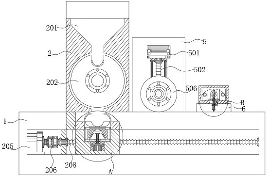
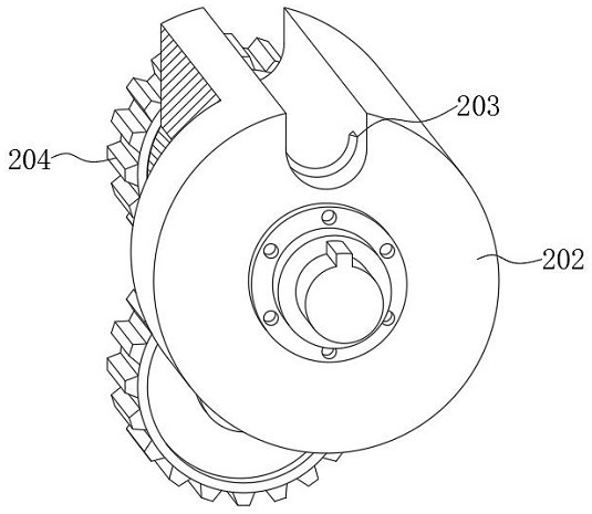
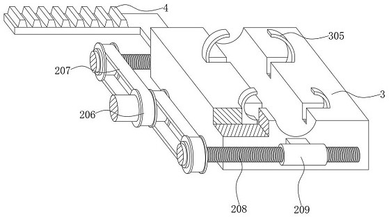
[0031] see Figure 1-8 , the present invention provides a technical solution: a non-standard buoyant pin with directional chipping detection processing inspection equipment, including a bottom chassis 1, the left side of the bottom chassis 1 is installed with a parts transmission assembly 2, the top of the parts transmission assembly 2 A feeding bin 201 is provided, and a feeding wheel 202 is installed below the bottom outlet of the feeding ...


PUM


Abstract

The present invention discloses a non-standard buoyancy lift pin machining inspection equipment with a directional trimming detection function. The equipment comprises a bottom machine box, a part conveying assembly is installed on the left side of the bottom machine box, and a trimming assembly is fixedly connected to the top end face of the bottom machine box through bolts; the part conveying assembly, the trimming assembly and the detection assembly are sequentially arranged on the top end face of the bottom case, and a positioning sliding seat is connected with the part conveying assembly, so that clearance conveying of the floating pin is facilitated, and meanwhile, the floating pin is clamped and fixed; and the situation that friction force drives the buoyancy lift pin to rotate in a memory mode when a grinding wheel rotates in the edge cutting process is avoided, the edge cutting assembly and the detection assembly are arranged, flatness detection can be conveniently conducted on the edge cutting part after edge cutting is conducted on the buoyancy lift pin, and therefore the situation that substandard buoyancy lift pins flow into the market to be used is avoided, and therefore, the quality of the buoyancy lift pin is controlled while the personnel operation is reduced and the efficiency is improved.

Description

technical field [0001] The invention relates to the technical field of lift pins, in particular to a processing inspection device for non-standard lift pins with directional edge-cutting detection. Background technique [0002] The lift pin is a mold accessory that is installed and guided on the stamping die, and one of the lift pins has a groove on the head, we call it a guide groove, and the lift pin relies on the three faces of this groove. There are three kinds of effects produced by material action. The upper groove surface is stripping, which is to separate the material from the positioning pin. The right groove surface restricts the left and right deviation of the material. Generally, there is a lifting pin on each side of the material width direction; The surface of the groove is the function of the buoyancy. Simply put, the buoyancy pin has the function of lifting, guiding, and stripping. , plastic steel buoyant pin, etc. [0003] When trimming the surface of the ...

Claims


Application Information

Patent Timeline
Patent Type & Authority Applications(China)
IPC IPC(8): G01B5/00
CPCG01B5/0002
Inventor 胡俊芳伍洲
Owner 深圳市优立检测技术服务有限公司
Why Eureka
Try Eureka