Unlock instant, AI-driven research and patent intelligence for your innovation.
Transportation equipment for rubber rods for tire processing
What is Al technical title?
Al technical title is built by PatSnap Al team. It summarizes the technical point description of the patent document.
A technology of transportation equipment and rubber rods, which is applied in the direction of transportation and packaging, conveyors, conveyor objects, etc., and can solve problems such as single function
Pending Publication Date: 2022-03-22
SHANDONG LINGLONG TIRE +1
View PDF5 Cites 0 Cited by
Summary
Abstract
Description
Claims
Application Information
AI Technical Summary
This helps you quickly interpret patents by identifying the three key elements:
Problems solved by technology
Method used
Benefits of technology
Problems solved by technology
[0002] The transportation equipment for processing rubber rods for tires is a commonly used equipment in the field of transportation equipment, but the general transportation equipment for processing rubber rods for tires has a single function
Method used
Image
Click on the blue label to locate the original text in one second.
Reading with bidirectional positioning of images and text.
Examples
specific Embodiment approach 1
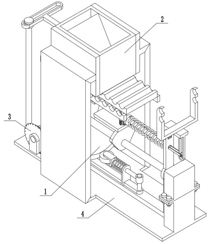
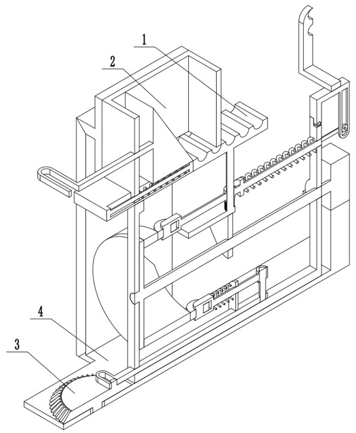
[0025] 1. Combine below Figure 1-9 Description of this embodiment, a transportation device for processing rubber rods for tires, including a carrying part 1, a material box assembly 2, a transmission assembly 3, and a connecting frame assembly 4, wherein the carrying part 1 is connected to the connecting frame assembly 4 Connection, the material box assembly 2 is connected with the connecting frame assembly 4, the transmission assembly 3 is connected with the carrying part 1, and the transmission assembly 3 is connected with the material box assembly 2;
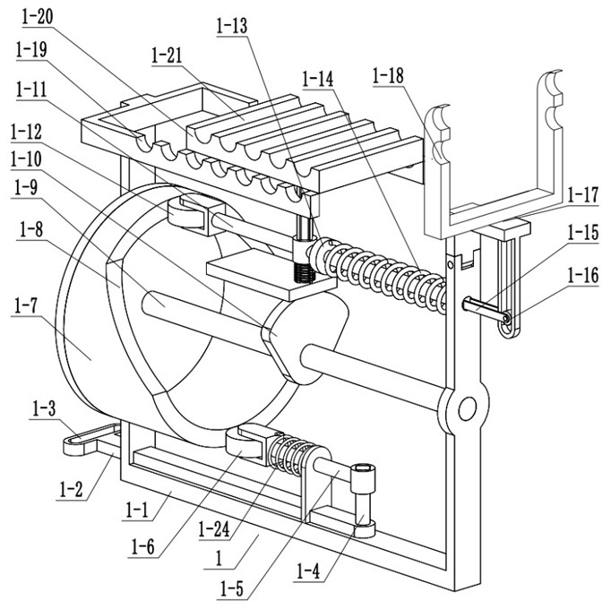
[0026]The carrying part 1 includes a carrying bracket 1-1, a lower end slide bar 1-2, a lower end matching chute 1-3, a hinge column 1-4, a lower end driving slide bar 1-5, a lower end driving roller 1-6, a driving Sleeve 1-7, outer edge 1-8, middle end rotating column 1-9, middle end cam 1-10, upper end driving slide rod 1-11, upper end driving roller 1-12, limit boss 1-13, Spring two 1-14, driving frame 1-15, driving fram...
specific Embodiment approach 5
[0030] Combine below Figure 1-9 Describe this embodiment. This embodiment will further explain Embodiment 1. The connecting frame assembly 4 includes a connecting frame body 4-1, a matching waist groove 4-2, an upper end fixing plate 4-3, an input motor 4-4, and a matching waist groove 4-2 is arranged on the connecting frame body 4-1, the upper fixing plate 4-3 is fixedly connected with the connecting frame body 4-1, the input motor 4-4 is fixedly connected with the connecting frame body 4-1, and the input motor 4-4 The output shaft is fixedly connected with the middle-end rotary column 1-9, the bevel gearturret 3-1 is fixedly connected with the inner end of the matching waist groove 4-2, and the upper end fixed plate 4-3 is fixedly connected with the outer frame 2-1 of the material box. The bracket 1-1 is fixedly connected with the carrying bracket 1-1.
[0031] A kind of transportation equipment for processing rubber rods for tires of the present invention, its working pr...
PUM
Abstract
The invention relates to the field of transportation equipment, in particular to transportation equipment for rubber rods for tire processing. And the transportation of the rubber rods for tire processing can be realized. Comprising a carrying part, a material box assembly, a transmission assembly and a connecting frame assembly, the carrying part is connected with the connecting frame assembly, the material box assembly is connected with the connecting frame assembly, the transmission assembly is connected with the carrying part, and the transmission assembly is connected with the material box assembly. When the bar clamping plate moves towards the left side, the closing plate is pushed to move towards the left side, then the rubber bar falls into a third bar clamping hole in the bar clamping plate through the material box outer frame, and along with clockwise movement of the bar clamping plate, the rubber bar in the third bar clamping hole falls into a first bar clamping hole.
Description
technical field [0001] The invention relates to the field of transportation equipment, in particular to a transportation equipment for processing rubber rods for tires. Background technique [0002] The transportation equipment for processing rubber rods for tires is a commonly used equipment in the field of transportation equipment, but the general transportation equipment for processing rubber rods for tires has a single function. Contents of the invention [0003] The object of the present invention is to provide a transportation device for processing rubber rods for tires, which can realize the transportation of rubber rods for processing tires. [0004] The purpose of the present invention is achieved through the following technical solutions: [0005] A transportation device for processing rubber rods for tires, comprising a carrying part, a material box assembly, a transmission assembly, and a connecting frame assembly, characterized in that: the carrying part ...
Claims
Application Information
Patent Timeline
Application Date:The date an application was filed.
Publication Date:The date a patent or application was officially published.
First Publication Date:The earliest publication date of a patent with the same application number.
Issue Date:Publication date of the patent grant document.
PCT Entry Date:The Entry date of PCT National Phase.
Estimated Expiry Date:The statutory expiry date of a patent right according to the Patent Law, and it is the longest term of protection that the patent right can achieve without the termination of the patent right due to other reasons(Term extension factor has been taken into account ).
Invalid Date:Actual expiry date is based on effective date or publication date of legal transaction data of invalid patent.
