Flexible adjustment eccentric clamp for numerical control lathe and implementation method of flexible adjustment eccentric clamp
A numerically controlled lathe and the technology of its implementation method, applied in the directions of turning equipment, manufacturing tools, accessories of tool holders, etc., can solve the problems of increased cost, low production efficiency, increased working hours, etc., and achieve the effect of saving cost and time, and improving production efficiency
- Summary
- Abstract
- Description
- Claims
- Application Information
AI Technical Summary
Problems solved by technology
Method used
Image
Examples
specific Embodiment
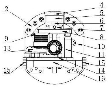
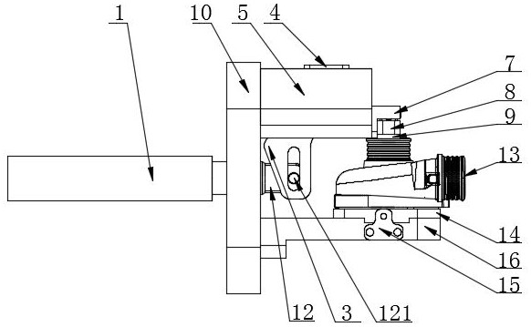
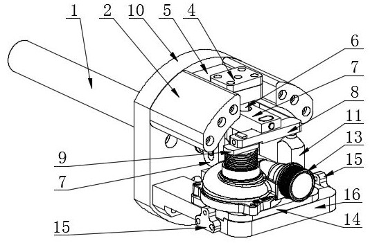
[0029] In this specific example, as figure 1 , figure 2 , image 3 , Figure 4 As shown, a flexible adjustable eccentric fixture for a CNC lathe and its implementation method, including a pull rod, a flange 10, a crank lever 7, a positioning block 5, a pressure plate, a support column 11, a configuration block 14 and a base plate 16;
[0030] The pull rod includes an oil cylinder tube 1 and a telescopic rod 12, the rod head of the telescopic rod 12 is set in a flat shape, and a first transparent circular hole is arranged in the horizontal direction; the telescopic rod 12 passes through the center of the flange 10 The central circular hole in the position is flexible;
[0031] The flange 10 is set as a metal block with circular arcs at both ends, and a transparent central circular hole is fixed at the center of the flange 10, and is fixed on the upper and lower parts of the flange 10 respectively. A number of screw holes are set; a tile-shaped wing block 2 is fixed on both...
Embodiment approach
[0041] The operator places the special-shaped part 13 to be processed on the positioning pin 142 on the left side of the top surface of the configuration block 14;
[0042] Further, the operator controls the retraction of the telescopic rod 12 of the pull rod, and drives the lower end of the vertical rod of the crank lever 7 to approach the flange 10, with the " The contact point between the auricle"-shaped arc 3 and the flange 10 is a lever fulcrum, causing the front end of the horizontal rod to press down on the pressure plate;
[0043] Further, the right end of the pressure plate bridge 8 in the pressure plate is supported by the support column 11 and cannot be lowered, so that the pressure plate 9 below the left end of the pressure plate bridge 8 presses down vertically. The special-shaped part 13 is tightly fixed to the special-shaped part 13;
[0044] Further, processing the special-shaped parts 13;
[0045] Further, the operator can loosen the pressing and fixing of the...
PUM
 Abstract
Description
Claims
Application Information
 - R&D
- Intellectual Property
- Life Sciences
- Materials
- Tech Scout
- Unparalleled Data Quality
- Higher Quality Content
- 60% Fewer Hallucinations
Browse by: Latest US Patents, China's latest patents, Technical Efficacy Thesaurus, Application Domain, Technology Topic, Popular Technical Reports.
© 2025 PatSnap. All rights reserved.Legal|Privacy policy|Modern Slavery Act Transparency Statement|Sitemap|About US| Contact US: help@patsnap.com


