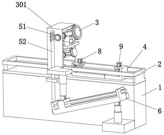
[0028] The technical solutions of the present invention will be clearly and completely described below in conjunction with the accompanying drawings. Apparently, the described embodiments are part of the embodiments of the present invention, but not all of them.
[0029] The components of the embodiments of the invention generally described and shown in the figures herein may be arranged and designed in a variety of different configurations. Accordingly, the following detailed description of the embodiments of the invention provided in the accompanying drawings is not intended to limit the scope of the claimed invention, but merely represents selected embodiments of the invention.
[0030] Based on the embodiments of the present invention, all other embodiments obtained by persons of ordinary skill in the art without making creative efforts belong to the protection scope of the present invention.
[0031] In the description of the present invention, it should be noted that the terms "center", "upper", "lower", "left", "right", "vertical", "horizontal", "inner", "outer" etc. The indicated orientation or positional relationship is based on the orientation or positional relationship shown in the drawings, and is only for the convenience of describing the present invention and simplifying the description, rather than indicating or implying that the referred device or element must have a specific orientation, or in a specific orientation. construction and operation, therefore, should not be construed as limiting the invention. In addition, the terms "first", "second", and "third" are used for descriptive purposes only, and should not be construed as indicating or implying relative importance.
[0032]In the description of the present invention, it should be noted that unless otherwise specified and limited, the terms "installation", "connection" and "connection" should be understood in a broad sense, for example, it can be a fixed connection or a detachable connection. Connected, or integrally connected; it can be mechanically connected or electrically connected; it can be directly connected or indirectly connected through an intermediary, and it can be the internal communication of two components. Those of ordinary skill in the art can understand the specific meanings of the above terms in the present invention in specific situations.
[0033] Combine below Figure 1 to Figure 6 As shown, the embodiment of the present invention provides a frame positioning tool for a concrete mixer truck, including a base 1, a slide rail 2 is fixedly installed above the base 1, and a positioning assembly 3, a clip A holding assembly 4, a transmission assembly 5 and a moving assembly 6, the holding assembly 4 is arranged above the base 1, the moving assembly 6 and the transmission assembly 5 are arranged on the side of the base 1, and the positioning assembly 3 includes a positioning frame 301, support plate 302, synchronization component 7, first positioning column 303, first electric push rod 304, first rotating shaft 305, two first bearing seats 306, first gear 307, second positioning column 308, second rotating shaft 309, two second bearing seats 310, a second gear 311 and a first hydraulic support rod 312, the positioning frame 301 is slidingly connected to the upper part of the slide rail 2, and the support plate 302 is arranged in the middle of the positioning frame 301, so The synchronization component 7 is arranged in the middle of the support plate 302, and the two first bearing seats 306 are fixedly installed above the support plate 302, and the first rotating shaft 305 is respectively connected to the two first bearing seats 306 in rotation, and the One end of the first rotating shaft 305 passes through the first bearing seat 306 and the positioning frame 301 on one side, the first positioning column 303 is fixedly installed in the middle of the first rotating shaft 305, and the first electric push rod 304 is fixedly installed on the support plate 302, and the telescopic end of the first electric push rod 304 is hinged to the middle of the positioning column, the first gear 307 is coaxially arranged on the first rotating shaft 305, and the two second bearing blocks 310 are fixedly installed Below the support plate 302, and the second rotating shaft 309 is respectively connected to the two second bearing housings 310 in rotation, the second positioning post 308 is fixedly installed in the middle of the second rotating shaft 309, and the first hydraulic support rod 312 is fixedly installed on the support plate 302, and the telescopic end of the first hydraulic support rod 312 is hinged to the middle of the positioning column, and the second gear 311 is coaxially arranged on the second rotating shaft 309 . The first positioning column 303 on the positioning component 3 is responsible for simulating the shape of the raised end of the mixing drum, so that the staff can install structures such as herringbone grooves here, and the second positioning column 308 is responsible for simulating the shape of the lower end of the mixing drum , so that the staff can install the mixing drum turret and other structures here, and the first hydraulic support rod 312 on the second positioning column 308 assists in supporting the second positioning column 308, improving the overall practicability of the device.
[0034] Specifically, the synchronization component 7 includes a fixed rod 71 and a first rack 72, the fixed rod 71 is fixedly mounted on the support plate 302, and the fixed rod 71 passes through the support plate 302, one of the fixed rods 71 A sliding slot is opened on the side, and the first rack 72 is slidably disposed in the fixed rod 71 , and the first gear 307 is engaged with the first rack 72 , and the second gear 311 is engaged with the first rack 72 . When the first positioning column 303 is raised, the first rotating shaft 305 rotates, thereby driving the coaxially arranged first gear 307 to rotate, and the first gear 307 meshes with the first rack 72 in the synchronous component 7, thereby driving the first gear 307 to rotate. A rack 72 slides, and the first rack 72 slides to drive the second gear 311 meshed with it to rotate, thereby driving the second rotating shaft 309 to rotate, so that the second positioning column 308 on the second rotating shaft 309 is also raised to match the first positioning position. The same angle of the columns 303 ensures that the angles at which the first positioning column 303 and the second positioning column 308 simulate the elevation of the mixing drum are consistent.
[0035] Specifically, the clamping assembly 4 includes a first clamping plate 41 and a second clamping plate 42, the first clamping plate 41 is fixedly installed above the base 1, and the second clamping plate 42 is connected to the second clamping plate 42. A clamping plate 41 is slidingly fitted, the first clamping plate 41 is provided with a first clamping component 8, and the second clamping plate 42 is provided with a second clamping component 9, and the first clamping plate 42 is provided with a second clamping component 9. One side of the plate 41 is provided with a first motor 43, the output end of the first motor 43 is fixedly connected with a first screw 44, the first screw 44 runs through the first clamping plate 41, and the first screw 44 It is threadedly connected with the second clamping plate 42 . The staff first places the frame of the concrete mixer truck in the clamping assembly 4 located on the base 1, and can start the first motor 43 in advance, and the first motor 43 drives the first screw 44 to rotate, thereby driving the second clamping plate 42 close to or away from the first clamping plate 41 to adjust the distance between the first clamping plate 41 and the second clamping plate 42, so as to adapt to different vehicle frame lengths, and then simultaneously start the 41 and the first clamping part 8 and the second clamping part 9 on the second clamping plate 42 carry out the work of centering, pressing and fixing the vehicle frame.
[0036] Specifically, the first clamping part 8 includes a first cylinder 81, a first pressing plate 82, a second motor 83, a first two-way screw 84 and two first clamping blocks 85, and the first cylinder 81 Arranged above the first clamping plate 41, the first pressing plate 82 is fixedly connected to the output end of the first cylinder 81, the second motor 83 is arranged on one side of the first clamping plate 41, the The first two-way screw 84 is fixedly connected to the output end of the second motor 83, and the two first clamping blocks 85 are respectively arranged at both ends of the first two-way screw 84 and threadedly connected with the first two-way screw 84, and two The first clamping blocks 85 are slidingly matched with the first pressing plates 82 respectively. Start the second motor 83, and the second motor 83 drives the first two-way screw rod 84 to rotate, thereby driving the two first clamping blocks 85 to approach each other, aligning one end of the vehicle frame to the central axis of the base 1, and then start the first Cylinder 81, the first cylinder 81 drives the first pressing plate 82 to move downwards to compress one end of the vehicle frame.
[0037] Specifically, the second clamping part 9 includes a second cylinder 91, a second pressing plate 92, a third motor 93, a second two-way screw 94 and two second clamping blocks 95, and the second cylinder 91 Arranged above the second clamping plate 42, the second pressing plate 92 is fixedly connected to the output end of the second cylinder 91, the third motor 93 is arranged on one side of the second clamping plate 42, the The second two-way screw 94 is fixedly connected to the output end of the third motor 93, and the two second clamping blocks 95 are respectively arranged at both ends of the second two-way screw 94 and threadedly connected with the second two-way screw 94, and two The second clamping blocks 95 are slidingly matched with the second pressing plates 92 respectively. Start the third motor 93, the third motor 93 drives the second two-way screw 94 to rotate, thereby driving two second clamping blocks 95 to approach each other, aligning one end of the vehicle frame to the central axis of the base 1, and then start the second The air cylinder 91 and the second air cylinder 91 drive the second pressing plate 92 to move downward to compress one end of the vehicle frame.
[0038] Specifically, the moving assembly 6 includes an adjustment rod 61 , a screw slide 62 , a second hydraulic support rod 63 , a connecting plate 64 , a fixed column 65 and a sliding column 66 , and one end of the adjustment rod 61 is rotatably connected to the base 1 , and the rotating shaft of the adjusting rod 61 is coaxially provided with a second worm gear 67, the screw slide 62 is fixedly connected to one side of the adjusting rod 61, and the second hydraulic support rod 63 is fixedly installed on the base 1 One side, and the telescopic end of the second hydraulic support rod 63 is hinged with one end of the screw slide 62, the connecting plate 64 is fixedly installed on one side of the positioning frame 301, and the bottom of the connecting plate 64 is fixedly installed There is a fixed column 65 , and a sliding column 66 is slidably connected in the fixed column 65 , and the bottom of the sliding column 66 is hinged with the slider on the screw slide table 62 . The slide block on the screw slide table 62 drives the sliding column 66 hinged therewith to move, and the sliding column 66 is slidably connected to the fixed column 65, the fixed column 65 is fixedly connected to the connecting plate 64, and the connecting plate 64 is fixedly connected to the positioning frame 301 , so that the slider on the screw slide table 62 can drive the positioning frame 301 to slide to the corresponding position on the slide rail 2 when moving, and then install the remaining workpieces on the frame of the concrete mixer truck, and the screw slide table The second hydraulic support rod 63 , which is hinged at one end of 62 , plays the role of auxiliary support for the screw slide table 62 and the adjusting rod 61 .
[0039] Specifically, the transmission assembly 5 includes a first worm wheel 51 and a worm 52, the first worm wheel 51 is coaxially arranged on the first rotating shaft 305, the worm 52 is rotationally connected with the base 1, and the two worms of the worm 52 The ends mesh with the second worm wheel 67 and the first worm wheel 51, respectively. When the first rotating shaft 305 rotates, it will drive the first worm gear 51 to rotate, and the first worm gear 51 drives the worm screw 52 on the transmission assembly 5 to rotate, and the rotation of the worm screw 52 drives the second worm gear 67 meshed with it to rotate, so that the adjusting rod 61 can also rotate. Rotating at the same angle as the first positioning column 303, the second hydraulic support rod 63 hinged at one end of the screw slide 62 plays the role of auxiliary support for the screw slide 62 and the adjusting rod 61, so that the screw on the adjusting rod 61 When the slide table 62 is working, the sliding column 66 hinged with it can be driven by the slider to move, and the sliding column 66 is slidably connected with the fixed column 65, the fixed column 65 is fixedly connected with the connecting plate 64, and the connecting plate 64 is fixed with the positioning frame 301 connection, so that the slider on the screw slide table 62 can drive the positioning frame 301 to slide to the corresponding position on the slide rail 2 when moving, and the rotation of the worm 52 and the base 1 is matched so that the first worm wheel 51 is disengaged without When the worm 52 is meshed, the worm 52 can also be kept stable, and then the rest of the workpieces on the frame of the concrete mixer truck are installed, so that the whole device only needs to input the length and elevation angle of the simulated mixing drum, without knowing the mixing drum The distance between the two ends in the horizontal direction reduces the operating error and improves the overall operating accuracy of the device.
[0040]Working principle: The first positioning column 303 on the positioning component 3 is responsible for simulating the shape of the raised end of the mixing drum, so that the staff can install structures such as herringbone grooves along the edge of the first positioning column 303 here, and according to the first positioning column 303 The shape of the middle part of a positioning column 303 is used to install structures such as the lower hopper, and the second positioning column 308 is responsible for simulating the shape of the lower end of the mixing drum, so that the staff can carry out structures such as the mixing drum turret along the edge of the second positioning column 308 here. For the installation, the staff first places the frame of the concrete mixer truck in the clamping assembly 4 on the base 1, and the first motor 43 can be started in advance, and the first motor 43 drives the first screw 44 to rotate, thereby driving the second The clamping plate 42 is close to or far away from the first clamping plate 41 to adjust the distance between the first clamping plate 41 and the second clamping plate 42, thereby adapting to different vehicle frame lengths. The first clamping part 8 and the second clamping part 9 on the clamping plate 41 and the second clamping plate 42 carry out the work of centering, pressing and fixing the frame, so that the frame of the concrete mixer truck can be kept on the base 1, to ensure that the follow-up welding and installation work can be carried out smoothly, take the first clamping part 8 as an example, start the second motor 83, and the second motor 83 drives the first two-way screw 84 to rotate, thereby driving the two first The clamping blocks 85 are close to each other, and one end of the vehicle frame is aligned to the central axis of the base 1, and then the first cylinder 81 is activated, and the first cylinder 81 drives the first pressing plate 82 to move downward, pressing one end of the vehicle frame. Tight, the second clamping part 9 uses the same working principle as the first clamping part 8 to press and fix the other end of the frame at the same time, and then activate the positioning assembly according to the inclination of the mixing drum that needs to be installed on the frame 3, the first electric push rod 304 on the first rotating shaft 305 is raised to the desired angle, and the first rotating shaft 305 rotates during the process of the first positioning post 303 being raised, thereby Drive the coaxial first gear 307 to rotate, and the first gear 307 meshes with the first rack 72 in the synchronous part 7, thereby driving the first rack 72 to slide, and the first rack 72 slides to drive the second rack 72 meshed with it. The gear 311 rotates, thereby driving the second rotating shaft 309 to rotate, so that the second positioning post 308 on the second rotating shaft 309 is also raised by the same angle as the first positioning post 303, ensuring that the first positioning post 303 is similar to the second positioning post 308 The raising angle of the mixing drum is consistent, and the first hydraulic support rod 312 on the second positioning column 308 assists in supporting the second positioning column 308, which improves the overall practicability of the device, and when the first rotating shaft 305 rotates, it will Drive the first worm gear 51 to rotate, and the first worm gear 51 drives the worm screw 52 on the transmission assembly 5 to rotate, and the rotation of the worm screw 52 drives the second worm gear 67 meshed with it to rotate, so that the adjusting rod 61 can also rotate the same as the first positioning post 303 Angle, the second hydraulic support rod 63 hinged at one end of the screw slide 62 plays the role of auxiliary support for the screw slide 62 and the adjusting rod 61, so that the screw slide on the adjusting rod 61 When 62 is working, the sliding column 66 hinged with it can be driven by the slider to move, and the sliding column 66 is slidably connected to the fixed column 65, the fixed column 65 is fixedly connected to the connecting plate 64, and the connecting plate 64 is fixedly connected to the positioning frame 301. The slide block on the screw slide table 62 can drive the positioning frame 301 to slide to the corresponding position on the slide rail 2 when moving, and the rotation cooperation between the worm 52 and the base 1 makes the first worm wheel 51 break away from the worm 52. When meshing, the worm 52 can also keep stable, and then install the other workpieces on the frame of the concrete mixer truck, so that the whole device only needs to input the length and elevation angle of the simulated mixing drum, without knowing the two ends of the mixing drum The distance in the horizontal direction reduces the operating error and improves the overall operating accuracy of the device.
[0041] Finally, it should be noted that: the above embodiments are only used to illustrate the technical solutions of the present invention, rather than limiting them; although the present invention has been described in detail with reference to the foregoing embodiments, those of ordinary skill in the art should understand that: It is still possible to modify the technical solutions described in the foregoing embodiments, or perform equivalent replacements for some or all of the technical features; and these modifications or replacements do not make the essence of the corresponding technical solutions deviate from the technical solutions of the various embodiments of the present invention. scope.