
Combined fan blade and combined air outlet device

An air outlet device and combined technology, which is applied to pump devices, components of pumping devices for elastic fluids, non-variable pumps, etc. Wind, affecting the wind pressure and air volume of the diagonal flow fan, etc., to achieve the effect of increasing the air volume and wind pressure

Pending Publication Date: 2022-03-25
续新电器技术(深圳)有限公司
View PDF0 Cites 0 Cited by
  • Summary
  • Abstract
  • Description
  • Claims
  • Application Information

AI Technical Summary

Problems solved by technology

[0002] Traditional high-pressure, high-speed fans are generally oblique flow fans. There is a hub in the middle of the oblique flow fan blades, and the air can only enter from the outside of the hub. As a result, there are some invalid air intake areas in the oblique flow fan, which affects the air intake of the oblique flow fan. , and the air forms a turbulent flow in this area, which interferes with the normal air intake of the diagonal flow fan and affects the wind pressure and air output of the diagonal flow fan

Method used


Image

  • Combined fan blade and combined air outlet device
  • Combined fan blade and combined air outlet device
  • Combined fan blade and combined air outlet device

Examples


Embodiment Construction

[0040] Embodiments of the present invention are described in detail below, examples of which are shown in the drawings, wherein the same or similar reference numerals designate the same or similar elements or elements having the same or similar functions throughout. The embodiments described below by referring to the figures are exemplary only for explaining the present invention and should not be construed as limiting the present invention.

[0041] In the description of the present invention, it should be understood that the orientation descriptions, such as up, down, front, back, left, right, etc. indicated orientations or positional relationships are based on the orientations or positional relationships shown in the drawings, and are only In order to facilitate the description of the present invention and simplify the description, it does not indicate or imply that the device or element referred to must have a specific orientation, be constructed and operated in a specific ...


PUM


Abstract

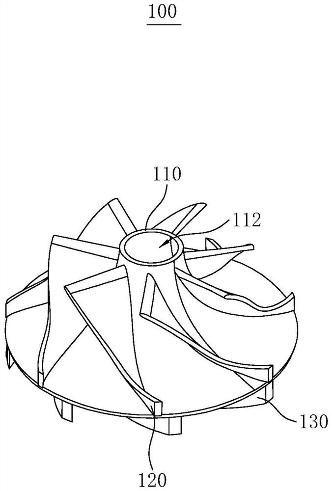
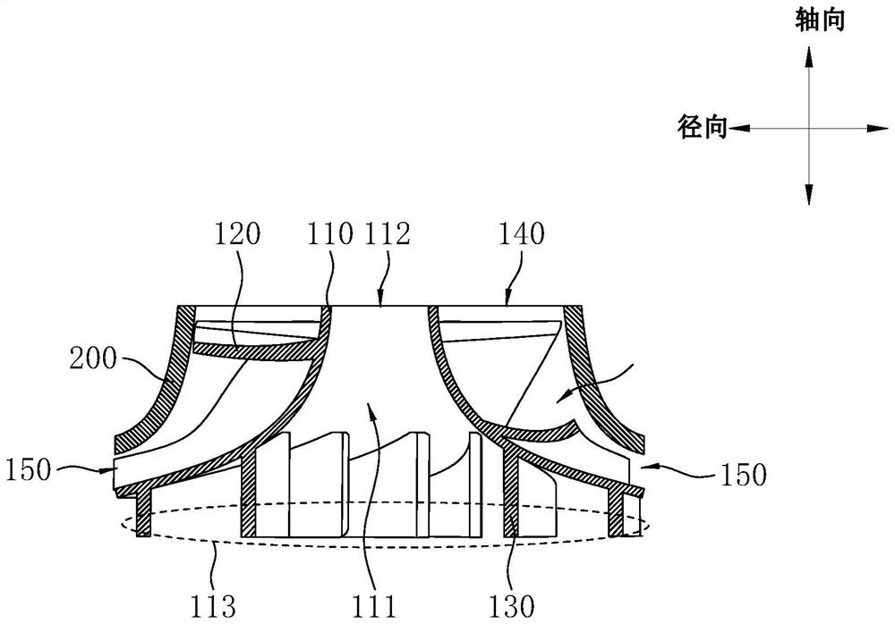
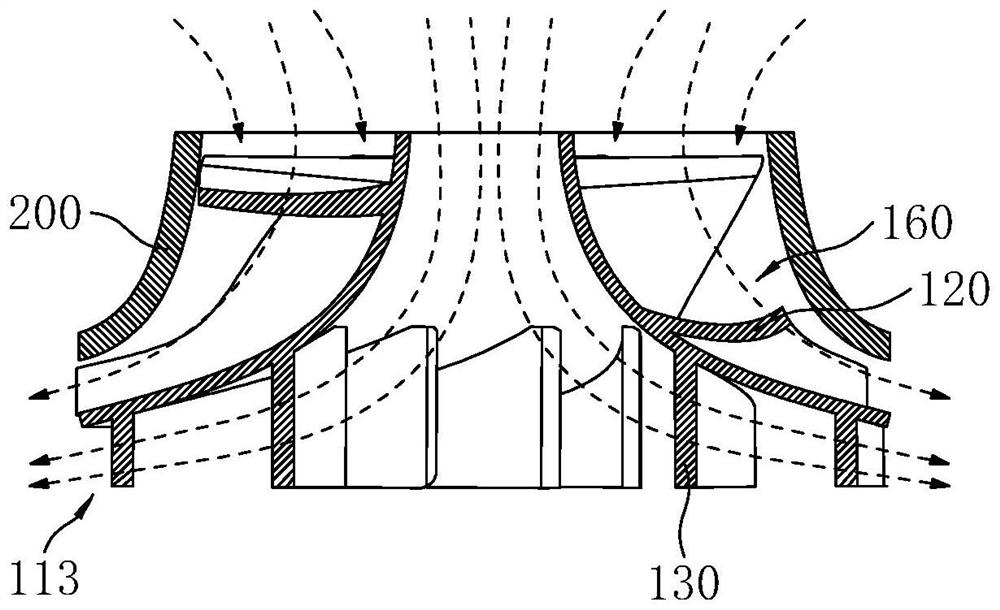
The invention discloses a combined fan blade and a combined air outlet device.The combined fan blade comprises a hub, oblique flow fan blades and centrifugal fan blades, a first air inlet is formed between the hub and a flow guide cover, the first end of the hub and the flow guide cover form a first air outlet, a second air inlet is formed in the first end of the hub, and the first air inlet is annularly formed in the outer side of the second air inlet; the second end of the hub is provided with a second air outlet, and the oblique flow fan blades and the centrifugal fan blades are connected to the two sides of the hub correspondingly. The combined air outlet device comprises the combined fan blade. According to the air outlet device, the air inlet area, on the air inlet side, of the hub can be fully utilized, the air inlet amount is increased, the oblique flow fan blades and the centrifugal fan blades can respectively form two paths of airflow, the two paths of airflow are converged after being discharged from the air outlet, and the air volume and the air pressure of the air outlet device can be effectively improved.

Description

technical field [0001] The invention relates to the technical field of air outlet structures, in particular to a combined fan blade and a combined air outlet device. Background technique [0002] Traditional high-pressure, high-speed fans are generally oblique flow fans. There is a hub in the middle of the oblique flow fan blades, and the air can only enter from the outside of the hub. As a result, there are some invalid air intake areas in the oblique flow fan, which affects the air intake of the oblique flow fan. , and the air forms a turbulent flow in this area, which interferes with the normal air intake of the diagonal flow fan and affects the wind pressure and air output of the diagonal flow fan. Contents of the invention [0003] The present invention aims to solve at least one of the technical problems existing in the prior art. Therefore, the present invention proposes a combined fan blade, which can make full use of the air inlet area of ​​the fan blade and incr...

Claims


Application Information

Patent Timeline
IPC IPC(8): F04D29/26F04D29/40F04D29/66F04D25/08
CPCF04D29/26F04D29/403F04D29/666F04D29/667F04D25/08
Inventor 张平胡善显廖俊杰谢智育孙兴林周慧珠孙叶琳骆兰英
Owner 续新电器技术(深圳)有限公司
Learn More