A test device for wave power conversion efficiency of a wave glider
A technology for power conversion and efficiency testing, which is used in measuring devices, instruments, surveying and mapping, and navigation.
Active Publication Date: 2022-06-03
OCEAN UNIV OF CHINA +2
View PDF7 Cites 0 Cited by
- Summary
- Abstract
- Description
- Claims
- Application Information
AI Technical Summary
Problems solved by technology
However, due to the complex and changeable offshore environment, and the difficulty of comprehensive observation of various operating conditions, it brings a lot of inconvenience to the efficiency optimization of tractors. The traditional wave simulation test mechanism has large size, poor adjustability, large transmission energy loss and resistance simulation. If the module is not perfect, it is difficult to accurately reflect the real motion state of the tractor. Therefore, a wave power conversion efficiency test device for the wave glider is needed to further optimize the wave power conversion efficiency of the wave glider.
Method used
View moreImage
Smart ImageViewing Examples
Examples
Embodiment Construction
Login to View More PUM
 Abstract
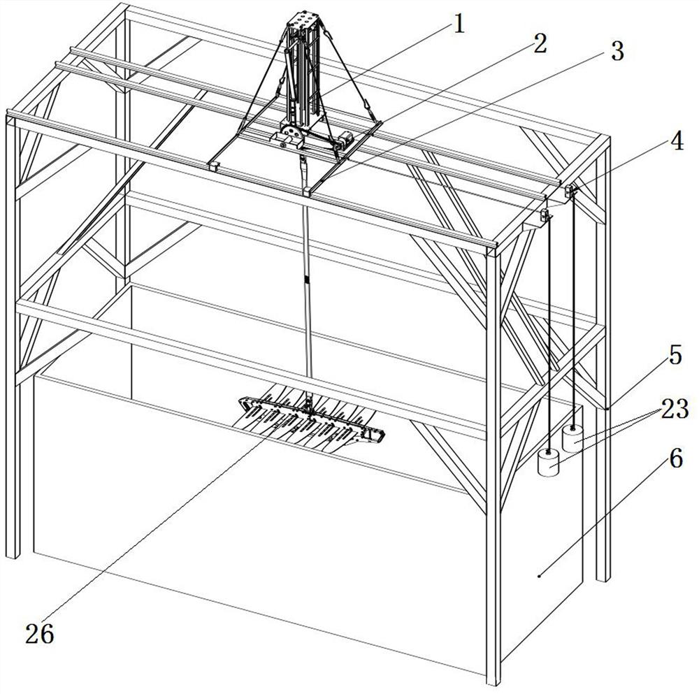
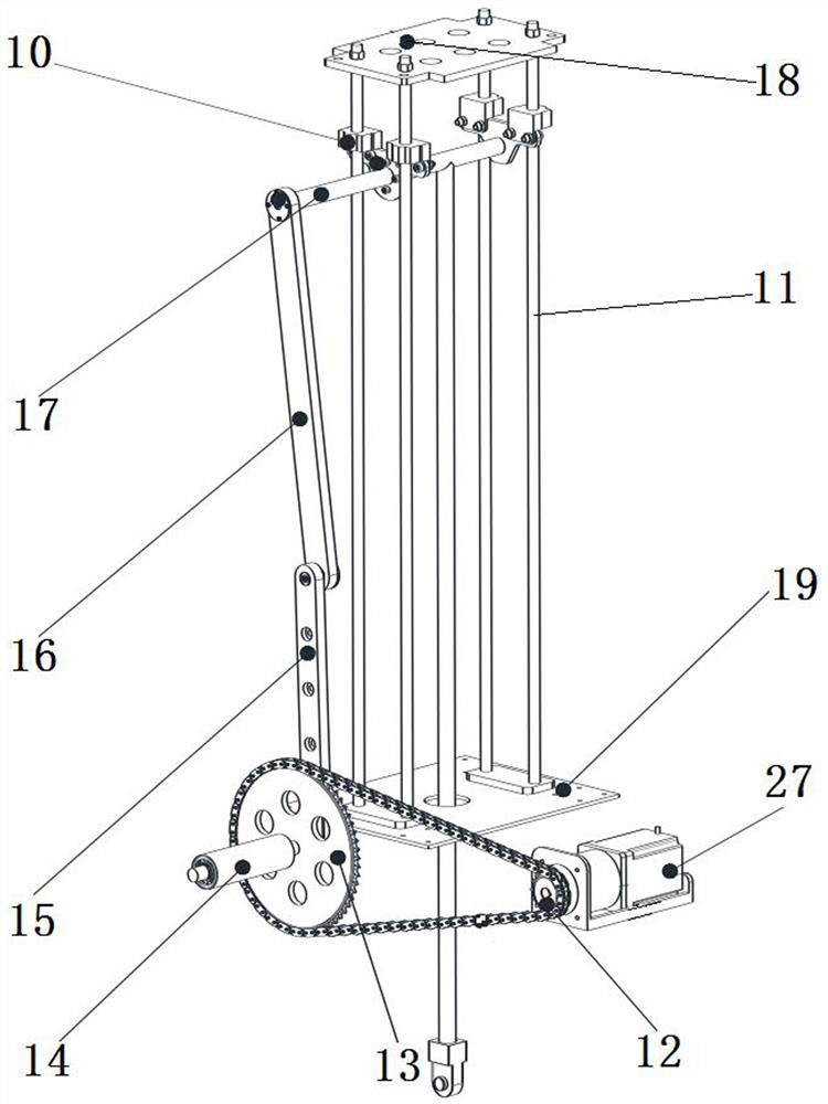
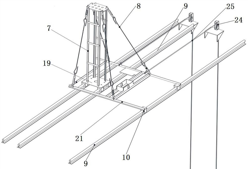
The invention discloses a wave power conversion efficiency test device for a wave glider, which relates to the technical field of wave glider research, and includes a frame, a driving mechanism, a lifting mechanism, a resistance simulation mechanism and a water tank, the driving mechanism is connected with the lifting mechanism, and the structure of the frame There is a lifting mechanism on the upper side and a water tank on the lower side. The lower end of the lifting mechanism is connected to the wave glider. The wave glider is located in the water tank filled with liquid. One end of the lifting mechanism is equipped with a resistance simulation mechanism. Swipe in the opposite direction. The invention adds a resistance simulation structure, has an adjustable resistance simulation structure, and can simulate different resistances; has a compact structure, is convenient to adjust, and can conduct experiments in a space with a small footprint.
Description
A test device for wave power conversion efficiency of a wave glider technical field The present invention relates to the technical field of wave glider research, particularly relate to a kind of wave glider wave power transfer [0001] Change the efficiency test device. Background technique [0002] The wave glider is a mobile platform for the observation of sea-air interface data, which can carry out long-distance, long-period Data collection of sea-air interface data in the open ocean. The underwater tractor of the wave glider is a precursor to converting wave energy into the entire device. The key part of the driving force is the core device that reflects the conversion efficiency of wave power. How to improve the wave of the wave glider Power conversion efficiency is a scientific problem that needs to be solved urgently. However, due to the complex and changeable offshore environment and the It is difficult to comprehensively observe the condition, which brings a...
Claims
Login to View More Application Information
Patent Timeline
 Patent Type & Authority Patents(China)
IPC IPC(8): G01C25/00G01C13/00
CPCG01C25/00G01C13/00Y02E10/30
Inventor 孙秀军桑宏强刘金成李灿王雷王力伟彭彬
Owner OCEAN UNIV OF CHINA
Features
- R&D
- Intellectual Property
- Life Sciences
- Materials
- Tech Scout
- Unparalleled Data Quality
- Higher Quality Content
- 60% Fewer Hallucinations
Learn More Browse by: Latest US Patents, China's latest patents, Technical Efficacy Thesaurus, Application Domain, Technology Topic, Popular Technical Reports.
© 2025 PatSnap. All rights reserved.Legal|Privacy policy|Modern Slavery Act Transparency Statement|Sitemap|About US| Contact US: help@patsnap.com


