
Sliding support structure and installation method thereof

A sliding bracket and fan technology, applied in the direction of instruments, electrical digital data processing, digital data processing components, etc., can solve the problems of not being able to move back and forth, not supporting space expansion, etc., and achieve the effect of flexible movement and flexible expansion of heat dissipation performance

Pending Publication Date: 2022-03-25
DONGGUAN RAMAXEL MEMORY TECH LTD
View PDF0 Cites 0 Cited by
  • Summary
  • Abstract
  • Description
  • Claims
  • Application Information

AI Technical Summary

Problems solved by technology

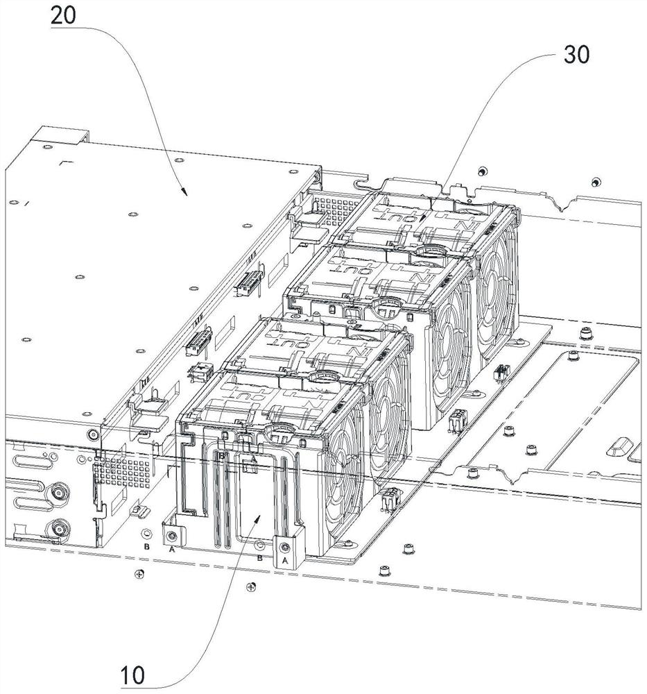
However, currently on the market, the uprights for fixing the upper cover lock, the cable management seats on both sides of the chassis, and the fan components are basically locked on the chassis, which cannot be moved back and forth, and does not support space expansion.

Method used


Image

  • Sliding support structure and installation method thereof
  • Sliding support structure and installation method thereof
  • Sliding support structure and installation method thereof

Examples


Embodiment Construction

[0029] In order to make the objectives, technical solutions and advantages of the present invention clearer, the present invention will be further described in detail below with reference to the accompanying drawings and specific embodiments.

[0030] The technical solutions in the embodiments of the present invention will be clearly and completely described below with reference to the accompanying drawings in the embodiments of the present invention. Obviously, the described embodiments are only a part of the embodiments of the present invention, but not all of the embodiments. Based on the embodiments of the present invention, all other embodiments obtained by those skilled in the art without creative efforts shall fall within the protection scope of the present invention.

[0031] In the description of the present invention, it should be understood that the terms "center", "longitudinal", "lateral", "length", "width", "thickness", "upper", "lower", "front", " Rear", "left",...


PUM


Abstract

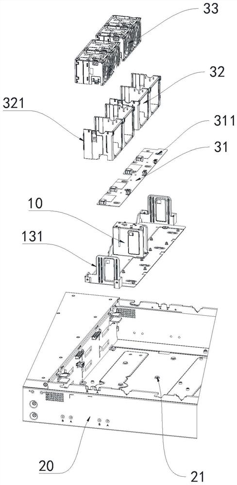
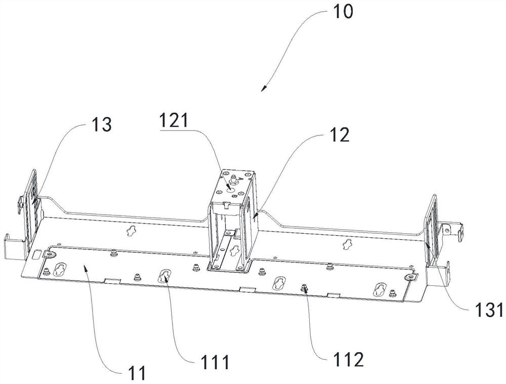
The invention relates to a sliding support structure and an installation method thereof, and the sliding support structure comprises a sliding support, a case and a fan assembly. The sliding support is connected with the case, and the fan assembly is connected with the sliding support; a plurality of cross-shaped groove holes are formed in the sliding support, I-shaped nails are arranged at the positions, corresponding to the cross-shaped groove holes, of the machine case, and the cross-shaped groove holes are connected with the I-shaped nails. Flexible movement of the whole fan assembly in the front-back direction of the case is achieved, space capable of being flexibly expanded and improving heat dissipation performance is provided, and wiring on the two sides of the case is not affected after the fan assembly moves by a certain distance.

Description

technical field [0001] The invention relates to the technical field of sliding support structures, in particular to a sliding support structure and an installation method thereof. Background technique [0002] With the improvement of server performance, the power consumption also increases, which brings great challenges to the conventional air-cooled heat dissipation of the whole machine. More space is needed to expand the performance of the radiator on the motherboard. However, in the current market, the upright column for fixing the cover lock, the cable management seat on both sides of the chassis, and the fan assembly are basically locked on the chassis, which cannot be moved back and forth, and does not support space expansion. SUMMARY OF THE INVENTION [0003] The purpose of the present invention is to overcome the deficiencies of the prior art and provide a sliding support structure and an installation method thereof. [0004] In order to solve the above-mentioned ...

Claims


Application Information

Patent Timeline
Patent Type & Authority Applications(China)
IPC IPC(8): G06F1/18G06F1/20
CPCG06F1/183G06F1/20
Inventor 张广艺邓志付剑
Owner DONGGUAN RAMAXEL MEMORY TECH LTD
Learn More