Scram button protection cover and use method

A protective cover and button technology, which is applied in the field of transportation, can solve the problems such as difficult to open the protective cover, stop driving, and difficult to press the emergency stop button in time, so as to prevent it from being difficult to open and improve the firmness

Pending Publication Date: 2022-03-25
NANJING COLLEGE OF INFORMATION TECH
View PDF0 Cites 0 Cited by
  • Summary
  • Abstract
  • Description
  • Claims
  • Application Information

AI Technical Summary

Problems solved by technology

[0003] 1. The pin is thin. When pulling out and inserting for a long time, the pin is prone to bending, causing the pin to be stuck between the top cover and the bottom frame and making it difficult to pull out. It is difficult to open the protective cover in a short time, resulting in an emergency stop button. Difficult to press in time
[0004] 2. The protective cover can only protect the outside of the emergency stop button. When the protective cover is opened, the operator touches the emergency stop button, and the emergency stop button is pressed when it is slightly touched. A false touch occurs, causing the train to Stop driving before reaching the stop position
[0005] 3. Existing emergency stop buttons have a variety of models, and the existing protective covers cannot adapt to different types of emergency stop buttons

Method used


Image

  • Scram button protection cover and use method
  • Scram button protection cover and use method
  • Scram button protection cover and use method

Examples


Embodiment 1

[0035] like Figure 1 to Figure 4 Shown:

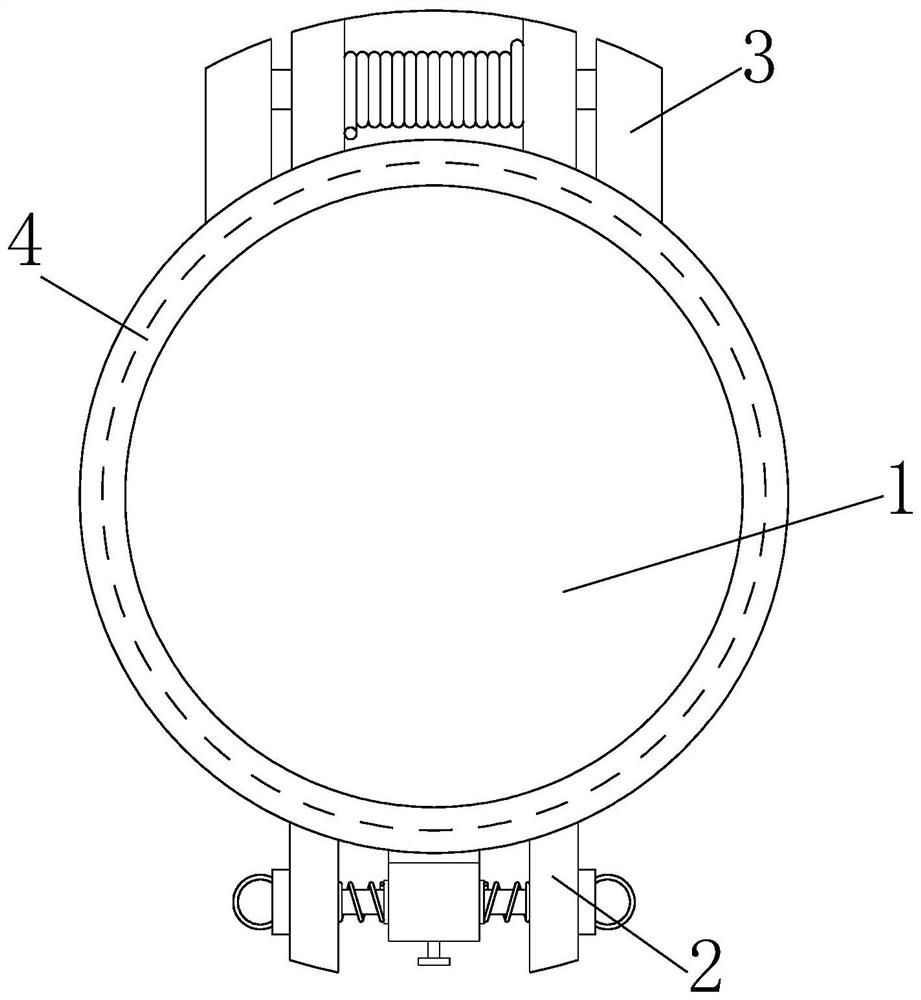
[0036] A protective cover for an emergency stop button, which is arranged outside the emergency stop button X, and includes a top cover 1, a clamping plate 2 and a protection mechanism 4;

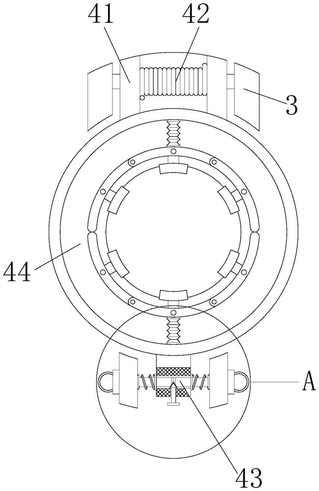
[0037] The protection mechanism 4 includes a protection frame 441 and an engaging mechanism 43; the protection frame 441 is cylindrical and hollow inside, and is vertically sleeved outside the emergency stop button X. Side; the engaging mechanism 43 is connected to the protective frame 441 , and the engaging mechanism 43 is arranged on the protective frame 441 between the two clamping plates 2 .

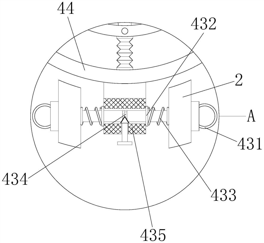
[0038]Engagement mechanism 43 comprises pull bar 431, spacer 432, spring 433, magnetic sheet 434 and separating mechanism 435; Pull bar 431, spacer 432, spring 433 and magnetic sheet 434 are all provided with two, are left-right symmetrical structure; A tie rod 431 runs through a clamping plate 2, a limiting piece 432 is welded to the middle end of a pu...

Embodiment 2

[0046] Such as Figure 5-6 As shown, on the basis of Embodiment 1, a nesting mechanism 44 is also included. The nesting mechanism 44 includes a telescopic hose 442 and a conflicting mechanism 443. The conflicting mechanism 443 includes a connecting plate 43a and a buckling plate 43c; the telescopic hose 442 and the interference mechanism 443 are two, symmetrically arranged inside the protective frame 441; one end of the telescopic hose 442 is connected to the inner wall of the protective frame 441, and the other end is connected to the connecting plate 43a, and the connecting plate 43a and the fastening plate 43c are arc-shaped plates , the height of the fastening plate 43c and the connecting plate 43a is greater than the rebound height of the emergency stop button X, and the fastening plate 43c is arranged on the inner wall of the connecting plate 43a. The bottom of the connecting plate 43a is provided with a slider, and the inner bottom of the protection frame 441 is provide...

Embodiment 3

[0051] Such as Figure 7 As shown, the resistance mechanism 443 also includes a push force mechanism 43d, which is arranged at the bottom of the emergency stop button X, and the push force mechanism 43d includes a spring rod d2, which has contractility, and there are multiple spring rods d2, which are arranged symmetrically on the inner bottom surface of the protective frame 441 .

[0052] The jacking mechanism 43d also includes a support plate d1, a top sheet d3 and a rubber pad d4; the support plate d1 is connected to the inner wall of the connecting plate 43a below the emergency stop button X, the support plate d1 is parallel to the emergency stop button X, and the spring rod d2 runs through the support plate d1, the upper end of the support plate d1 is provided with a top piece d3, and a rubber pad d4 is pasted on the top piece d3. The rubber pad d4 has a wrinkled structure and has a certain resilience, so as to improve the resilience of the bottom of the emergency stop b...


PUM


Abstract

The emergency stop button protection cover structurally comprises a top cover, a clamping plate, a rear supporting plate and a protection mechanism, the clamping plate is fixedly installed at one end of the top cover, the rear supporting plate is arranged at the other end of the top cover, the protection mechanism is located at the bottom of the top cover, and a push rod is pushed to enable a top block to rapidly separate the adsorption end faces of two magnetic sheets. A pull rod is separated from the interior of a clamping frame, in the separation process, through auxiliary rotation of a ball, the pull rod is prevented from being clamped in the clamping frame, the situation that a top cover is difficult to open is prevented, and a clamping plate rapidly opens the top cover from the front end of the nesting mechanism; the firmness of clamping connection between the top cover and the nesting mechanism is improved through magnetic adsorption between the two magnetic sheets, the jacking force mechanism is located at the bottom of the scram button and can protect different scram buttons, and the bottom of the scram button abuts against the rubber pad during pressing, so that the scram button is prevented from being damaged. The sudden stop button needs to be pressed forcibly, so that the top piece presses the spring rod downwards, and the sudden stop button is prevented from being touched by mistake.

Description

technical field [0001] The invention relates to the field of transportation, in particular to a protective cover for an emergency stop button and a use method thereof. Background technique [0002] Modern transportation mainly includes railways and urban rails, roads, waterways, aviation and pipelines. Emergency stop buttons are installed on railway transportation platforms. Emergency stop buttons can accurately stop trains that need to stop. Emergency stop buttons need external A protective cover is installed to prevent the emergency stop button from being accidentally touched, but because the top cover on the existing emergency stop button protective cover and the bottom outer frame are engaged and fixed by a latch, the existing fixing method still has the following problems : [0003] 1. The pin is thin. When pulling out and inserting for a long time, the pin is prone to bending, causing the pin to be stuck between the top cover and the bottom frame and making it difficu...

Claims


Application Information

Patent Timeline
IPC IPC(8): H01H13/04
CPCH01H13/04
Inventor 段付德王红然张世刚李昕颖杨伟智薛佳斌毛星雨朱锐罗浪宋宇翔王浩浩张纪元王钧岭赵毅刘沈磊李健段增奥郑啊强孙宇凡葛成王保来李沐晨封熙成汤德杰关纯子仇鑫源解亚丽
Owner NANJING COLLEGE OF INFORMATION TECH
Why Eureka
Try Eureka