LED support manufacturing method, LED support, packaging structure and backlight module

A technology for LED brackets and manufacturing methods, which is applied in the direction of electrical components, circuits, semiconductor devices, etc., can solve the problems of short distance of light guide plates, high requirements for light alignment, and small LED luminous angles, so as to increase LED luminous angles and reduce The number of LEDs used and the effect of increasing the side light intensity

Pending Publication Date: 2022-03-25
APT ELECTRONICS
View PDF0 Cites 0 Cited by
  • Summary
  • Abstract
  • Description
  • Claims
  • Application Information

AI Technical Summary

Problems solved by technology

The optical part of the conventional side-entry TV is composed of LED Light Bar and LED lamp beads. Due to the high requirements for light alignment, the distance between the LED and the light guide plate is short, and the LED light-emitting angle is small, the number of LEDs required is large, resulting in increased costs.

Method used


Image

  • LED support manufacturing method, LED support, packaging structure and backlight module
  • LED support manufacturing method, LED support, packaging structure and backlight module
  • LED support manufacturing method, LED support, packaging structure and backlight module

Examples


Embodiment 1

[0033] This embodiment discloses a method for manufacturing an LED bracket, which includes the following steps:

[0034] S1. Form a white plastic material layer above the metal layer electrodes; the white plastic material layer can be formed by injection molding or molding process.

[0035] S2. Before the white plastic layer is solidified and formed, spaces are reserved on the tops of the two opposite sides; the shape of the spaces is a cuboid.

[0036] S3. Use a high-precision glue dispenser to place transparent or translucent silicone on the empty space.

[0037] S4, drying silica gel.

[0038] Specifically, in step S2, the height reserved for the vacancy is greater than 1 / 6 of the complete height of the white plastic material layer, or equal to 1 / 6 of the complete height of the white plastic material layer.

Embodiment 2

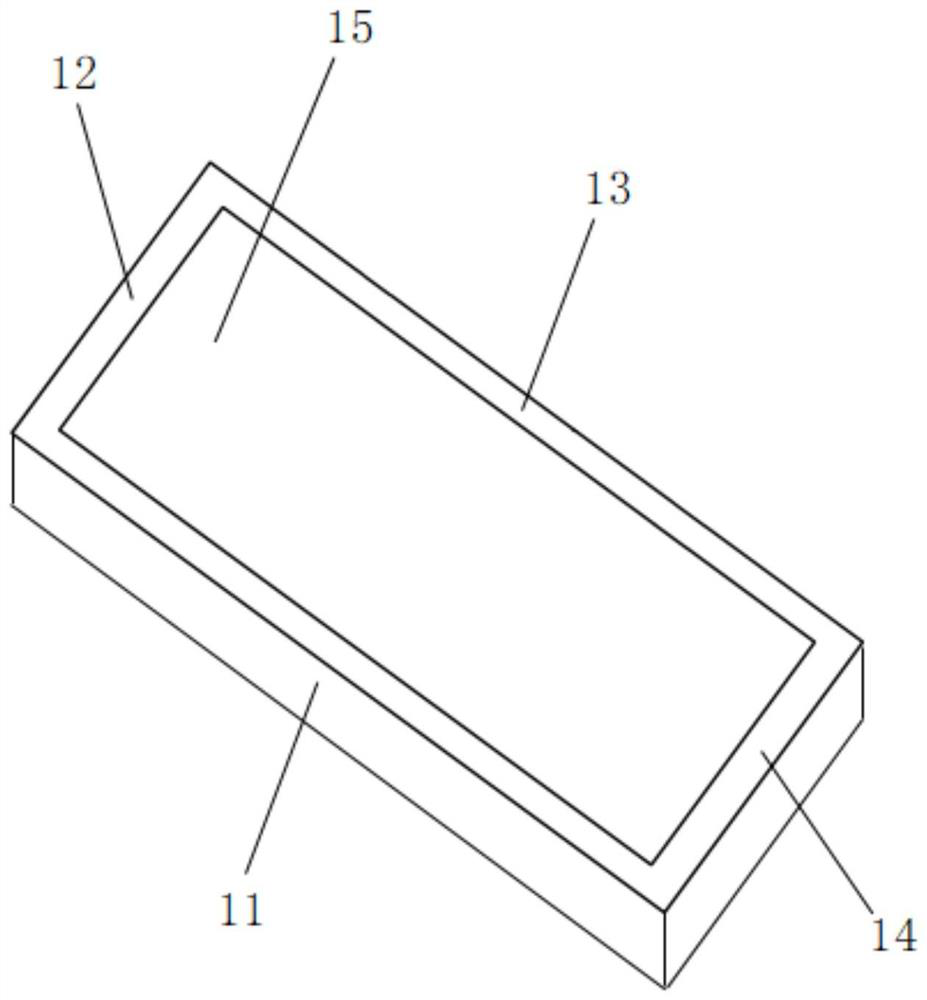
[0040] Such as figure 1 , this embodiment discloses an LED bracket, which is manufactured by using the LED bracket manufacturing method described in Embodiment 1, and includes a metal layer electrode and a bracket body, and the bracket body includes two opposite first side plates 11, 13 and two Two opposite second side plates 12 , 14 , two opposite first side plates 11 , 13 and two opposite second side plates 12 , 14 are connected to form an accommodating cavity 15 .

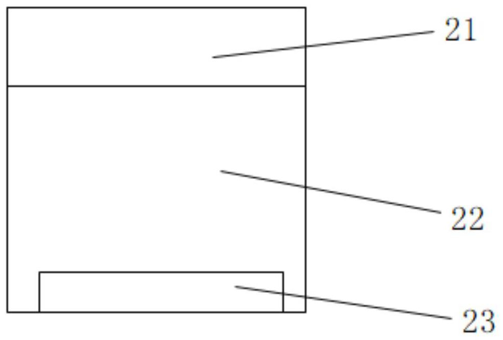
[0041] The first side panels 11, 13 are made of opaque materials, such as figure 2 , the second side plates 12, 14 include a transparent material layer 21 and an opaque material layer 22, the transparent material layer 21 is arranged on the opaque material layer 22, and the bottom of the opaque material layer 22 is provided with a metal layer electrode 23.

[0042] Specifically, the height of the transparent material layer 21 is greater than 1 / 6 of the depth of the accommodating cavity 15 , or equal to 1 / 6 of ...

Embodiment 3

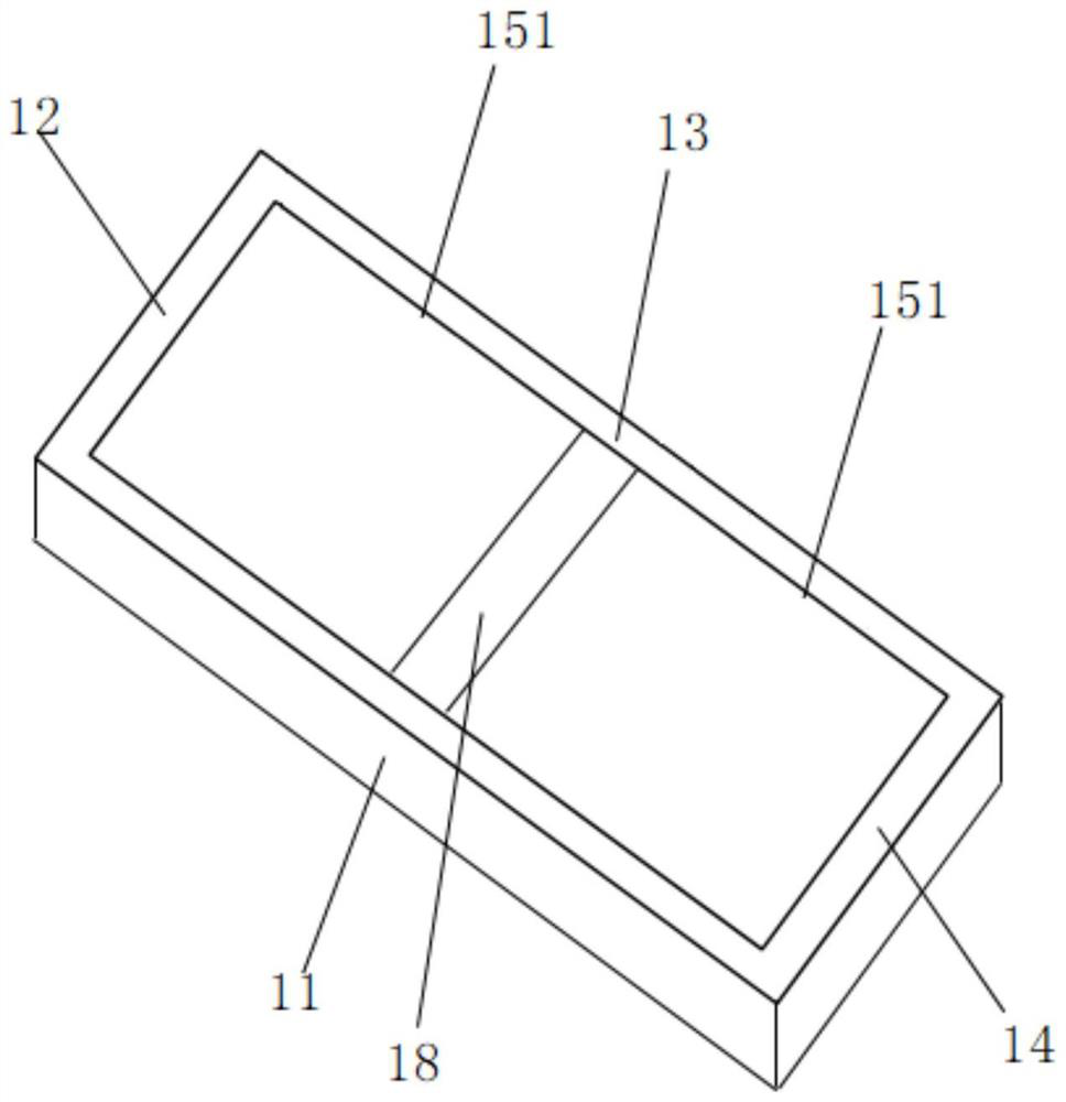
[0045] Such as image 3 , this embodiment discloses another LED bracket, which is manufactured by using the LED bracket manufacturing method described in Embodiment 1, and includes a metal layer electrode and a bracket body, and the bracket body includes two opposite first side plates 11, 13 and Two opposite second side plates 12, 14, two opposite first side plates 11, 13 are connected with two opposite second side plates 12, 14 to form an accommodating cavity, and a baffle plate 18 is arranged in the accommodating cavity The two ends of the baffle plate 18 are respectively connected with the two opposite first side plates 11, 13 to form two small accommodating cavities 151, and the baffle plate 18 is made of opaque material.

[0046] For other details of this embodiment, please refer to the foregoing embodiment, and details are not repeated here.


PUM


Abstract

The invention discloses an LED support manufacturing method, an LED support, a packaging structure and a backlight module. The manufacturing method comprises the following steps that S1, a white plastic material layer is formed above a metal layer electrode; s2, before the white plastic material layer is solidified and formed, vacancies are reserved in the tops of the two opposite side faces of the white plastic material layer; s3, dispensing silica gel at the vacancy by using a dispensing machine; s4, drying the silica gel; according to the invention, the side light intensity can be increased, the brightness of the LED is not reduced, the number of used LEDs is reduced, and the cost is reduced.

Description

technical field [0001] The invention belongs to the technical field of LEDs, and in particular relates to a manufacturing method of an LED bracket, an LED bracket, a packaging structure and a backlight module. Background technique [0002] Side-entry TVs have become the mainstream of today's TVs due to their small size and thin thickness. The optical part of the conventional side-entry TV is composed of LED Light Bar and LED lamp beads. Due to the high requirements for light alignment, the distance between the LED and the light guide plate is short, and the LED light-emitting angle is small, the number of LEDs required is large, resulting in increased costs. . Contents of the invention [0003] In order to overcome the above-mentioned technical defects, the first aspect of the present invention provides a method for manufacturing an LED bracket, which can increase the side light intensity and at the same time ensure that the brightness of the LED does not decrease, reduce...

Claims


Application Information

Patent Timeline
Patent Type & Authority Applications(China)
IPC IPC(8): H01L33/48H01L33/54
CPCH01L33/48H01L33/54H01L2933/0033
Inventor 龙小凤万垂铭姚述光曾照明区伟能肖国伟
Owner APT ELECTRONICS
Why Eureka
Try Eureka