
Locking switching mechanism of rotary operating handle and concrete cutting machine

A technology for operating a handle and a switching mechanism, which is applied in the directions of roads, road repairs, roads, etc., and can solve the problems such as the deviation of the blade 71 from the set value.

Active Publication Date: 2022-03-29
MIKASA SANGYO KK
View PDF10 Cites 0 Cited by
  • Summary
  • Abstract
  • Description
  • Claims
  • Application Information

AI Technical Summary

Problems solved by technology

[0009] In the case of cutting operations by a concrete cutting machine, in the state where the blade 71 is rotated at a high speed, the rotary operation handle (lifting handle) is rotated to adjust the depth of the blade 71. If the blade 71 reaches the set depth, then Manually operate and fix the locking mechanism (not shown) so that the rotary operation handle does not rotate, and advance the concrete cutting machine along a predetermined line. However, if the operation of the locking mechanism is forgotten and the cutting operation is continued, the Due to the vibration of the body itself or the impact from the outside, the rotary operation handle may rotate against the intention (misoperation), and in this case, there is a problem that the depth of the blade 71 deviates from the set value.

Method used


Image

  • Locking switching mechanism of rotary operating handle and concrete cutting machine
  • Locking switching mechanism of rotary operating handle and concrete cutting machine
  • Locking switching mechanism of rotary operating handle and concrete cutting machine

Examples


Embodiment Construction

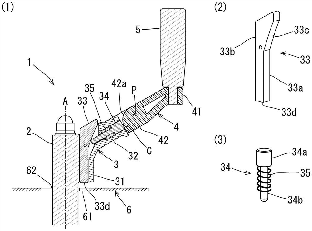
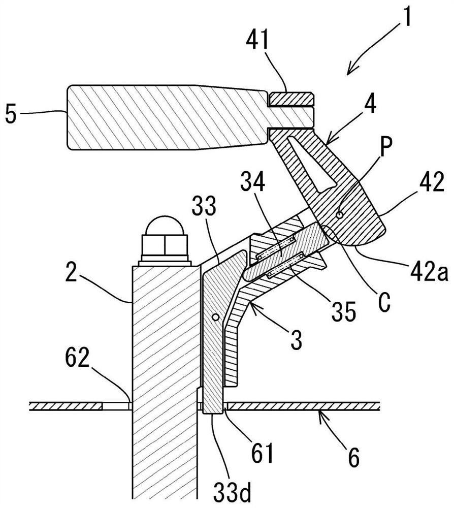
[0059] Hereinafter, an embodiment of a "lock switching mechanism for a rotary operating handle" (hereinafter simply referred to as "lock switching mechanism") of the present invention will be described with reference to the drawings. figure 1 (1) is an explanatory diagram of a first embodiment in which the lock switching mechanism of the present invention is applied to a lift handle (rotary operating handle) of a concrete cutting machine, and is a cross-sectional view of the lift handle 1 (lock release state), figure 1 (2) is a perspective view of the locking pin 33, figure 1 (3) is a perspective view of the follower pin 34 . in addition, figure 2 yes figure 1 A sectional view of the locked state of the lifting handle 1 shown.

[0060] The lifting handle 1 is composed of a handle shaft 2 (rotation shaft), a handle bracket (fixed part 3 , movable part 4 ), and a handle 5 . Among them, the handle shaft 2 is rotatably supported around the center axis A by a bearing not s...


PUM


Abstract

The invention provides a lock switching mechanism of a rotary operation handle and a concrete cutting machine, which can automatically lock or unlock a handle shaft in non-operation so as to avoid malfunction. The handle bracket is provided with a handle shaft (2) and consists of a fixed part (3) and a movable part (4); a pair of locking elements (a locking pin (33) and an engaging part (61)) capable of locking the handle shaft with respect to other elements by engaging; and a transmission mechanism for transmitting a force for operating the lock element, the fixed part (3) having a base end part (31) and a protruding part (32), the movable part (4) being pivoted with respect to the protruding part (32) so as to be rotatable from an extended state to a bent state and being biased in the direction of bending, the movable part (4) being connected to the lock element via the transmission mechanism, and the movable part (4) being biased in the direction of bending so as to be rotatable from the extended state to the bent state. The rotation of the movable part (4) causes the lock element (lock pin (33)) to operate.

Description

technical field [0001] The invention relates to a locking and switching mechanism of a rotary operating handle in working machines such as a concrete cutting machine for cutting or cutting asphalt pavement or concrete surfaces of roads, and the concrete cutting machine. Background technique [0002] Among various work machines, there is a work machine including a rotary operating handle. For example, in concrete cutting machines for cutting or cutting asphalt pavements or concrete surfaces of roads, a rotary operating handle (elevating handle) is often equipped as an operating element for adjusting the depth of the blade. [0003] Specifically, a general concrete cutting machine such as Figure 6 As shown, the body frame 72 is supported by wheels (front wheels 73 and rear wheels 76), and the blade 71 is supported on the side of the front portion of the body frame 72. ) receives the driving force to rotate at high speed. [0004] The front wheel 73 is supported by the front...

Claims


Application Information

Patent Timeline
Patent Type & Authority Applications(China)
IPC IPC(8): E01C23/09
CPCE01C23/0933
Inventor 村本健一堀口数马
Owner MIKASA SANGYO KK
Learn More