Gear linkage structure for compressor, compressor, outdoor unit and air conditioning system

A technology of gear linkage and compressor, applied in air-conditioning systems, compressors, machines/engines, etc., can solve the problem that the compressor cannot realize one-way operation, and achieve the effects of improving lifespan, reducing costs and improving reliability.

Pending Publication Date: 2022-03-29
GREE ELECTRIC APPLIANCES INC
View PDF0 Cites 0 Cited by
  • Summary
  • Abstract
  • Description
  • Claims
  • Application Information

AI Technical Summary

Problems solved by technology

[0005] One of the objectives of the present invention is to propose a gear linkage structure for compressors, which solves the technical problem that the compressors in the prior art cannot realize one-way operation

Method used


Image

  • Gear linkage structure for compressor, compressor, outdoor unit and air conditioning system
  • Gear linkage structure for compressor, compressor, outdoor unit and air conditioning system
  • Gear linkage structure for compressor, compressor, outdoor unit and air conditioning system

Examples


Embodiment 1

[0045] This embodiment describes in detail the gear linkage structure used in the compressor of the present invention.

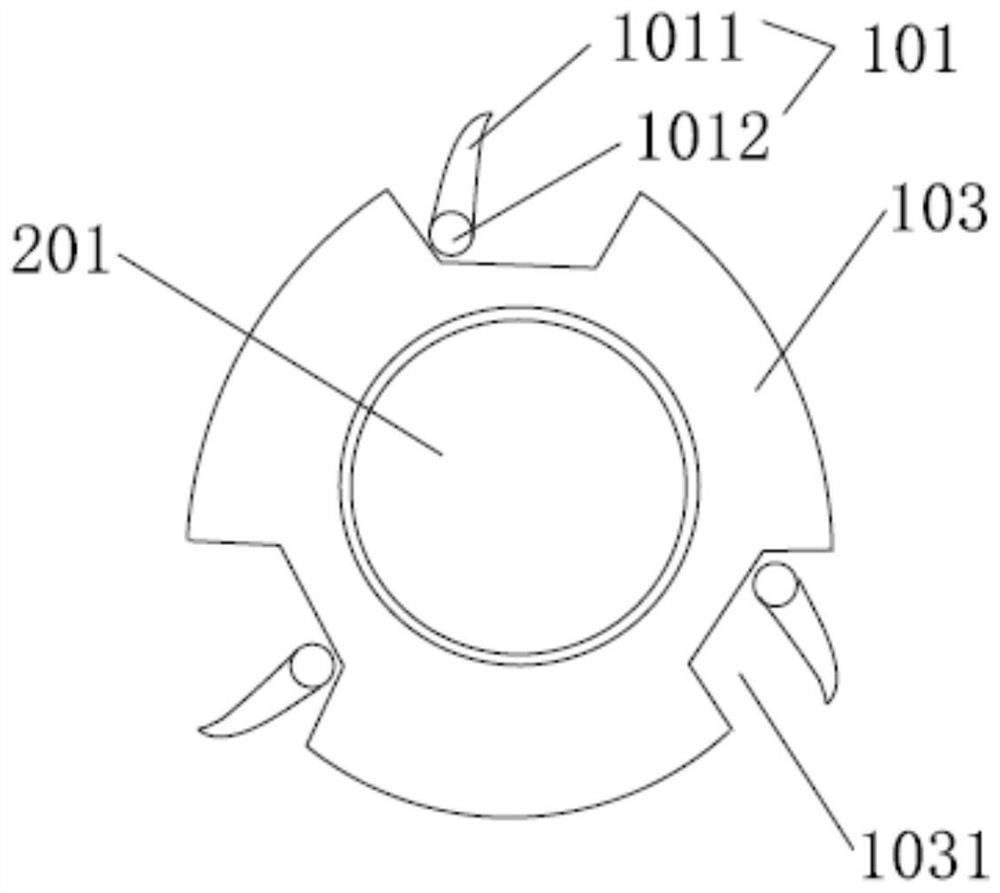
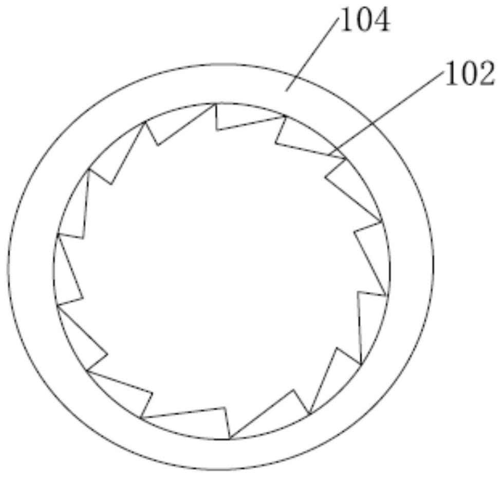
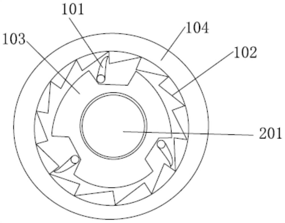
[0046]This embodiment is used for the gear linkage structure of the compressor, including the jack assembly 101 and the gear 102, such as Figure 1~3 shown. Preferably, the jack assembly 101 is connected to the first shaft 201 of the compressor and makes the steering of the jack assembly 101 consistent with the steering of the first shaft 201, and when the motor drives the first shaft 201 to rotate forward, the jack assembly 101 rotates forward and pushes the gear 102 drives the compressor body to rotate forward; when the motor drives the first rotating shaft 201 to reverse, the jack assembly 101 reverses and receives the pressure of the gear 102. The force required to rotate, the compressor body remains static, such as Figure 1~3 shown. The forward rotation mentioned in this embodiment may be clockwise rotation, correspondingly, reverse rotation is coun...

Embodiment 2

[0061] This embodiment describes the compressor of the present invention in detail.

[0062] The compressor in this embodiment includes a compressor body and a gear linkage structure. Preferably, the gear linkage structure is the gear linkage structure used in any one of the technical solutions in Embodiment 1 for the compressor. The structure of the compressor body can be the same as that of the prior art, and will not be repeated here.

[0063] The compressor of this embodiment includes any one of the technical solutions in Embodiment 1 for the gear linkage structure of the compressor. Through the action of the gear linkage structure, the compressor body can realize one-way operation, avoiding the reverse rotation of the compressor The resulting wear and tear of parts improves the reliability of the compressor operation, improves the service life and environmental tolerance of the compressor, cancels the anti-reverse protection measures of the compressor, and reduces the co...

Embodiment 3

[0065] This embodiment describes the outdoor unit of the present invention in detail.

[0066] The outdoor unit of this embodiment includes an outdoor unit body and a compressor. Preferably, the compressor is the compressor of any one of the technical solutions in Embodiment 2. The structure of the outdoor unit body can be the same as that of the prior art, and will not be repeated here.

[0067] The outdoor unit of this embodiment includes the compressor of any one of the technical solutions in Embodiment 2. Through the function of the compressor, the reliability of the operation of the outdoor unit can be improved, the life of the outdoor unit can be increased, and the cost of the outdoor unit can be reduced.


PUM


Abstract

The invention discloses a gear linkage structure for a compressor, the compressor, an outdoor unit and an air conditioning system, relates to the technical field of air conditioners, and solves the technical problem that the compressor cannot realize one-way operation in the prior art. The gear linkage structure for the compressor comprises a jack assembly and a gear, the jack assembly is connected with a first rotating shaft of the compressor, the rotating direction of the jack assembly is consistent with that of the first rotating shaft, and when a motor drives the first rotating shaft to rotate forwards, the jack assembly rotates forwards and pushes the gear to drive a compressor body to rotate forwards; when the motor drives the first rotating shaft to rotate reversely, the jack assembly rotates reversely and bears pressure of the gear, acting force transmitted by the jack assembly to the gear is smaller than acting force needed by the gear to drive the compressor body to rotate reversely, and the compressor body is kept in a static state. According to the gear linkage structure for the compressor, through cooperation of the jack assembly and the gear, one-way operation of the compressor body can be achieved, that is, the compressor can only rotate forwards.

Description

technical field [0001] The invention relates to the technical field of air conditioning, in particular to a gear linkage structure for a compressor, a compressor, an outdoor unit and an air conditioning system. Background technique [0002] With the advancement of science and technology, air conditioners are more and more widely used in various fields, including households, automobiles, subways, airplanes and other fields. Air conditioners have brought great convenience to people, and compressors, as the core components of air conditioners, are like the heart. Drive the stable operation of the entire air conditioning system. [0003] The working principle of the existing compressor is as follows: the motor drives the rotation shaft of the compressor to rotate, and the rotation of the rotation shaft drives the operation of the compressor body to realize gas compression. If the motor rotates forward, the rotating shaft rotates forward and drives the compressor body to rotate ...

Claims


Application Information

Patent Timeline
Patent Type & Authority Applications(China)
IPC IPC(8): F04C29/00F04C18/10F04C23/02F04C28/28F25B31/00F24F1/08
CPCF04C18/082F04C18/084F04C18/10F04C23/02F04C29/00F04C28/28F25B31/00F24F1/08
Inventor 梅正茂高杰金卫李赛陈洪楷
Owner GREE ELECTRIC APPLIANCES INC
Why Eureka
Try Eureka