Roller cleaning device with automatic regulation and control function for conveying roller way

A function and roll cleaning technology, which is applied in the field of aluminum processing hot rolling mill roller table cleaning, can solve the problems of high labor cost, uncoordinated width, and affecting equipment use, and achieve the effects of reducing manpower input, improving safety, and facilitating adjustment

Pending Publication Date: 2022-07-22
河南义瑞新材料科技有限公司
View PDF0 Cites 0 Cited by
  • Summary
  • Abstract
  • Description
  • Claims
  • Application Information

AI Technical Summary

Problems solved by technology

[0006] 1. The production pace of the hot rolling mill is fast and the quality requirements are high. The grinding, cleaning and wiping of the traditional conveyor roller clearing device is inefficient and affects the use of equipment
[0007] 2. Manually adjust the sandpaper, manually adjust the pressure roller to fix the sandpaper / cleaning cloth, and manually clean / wipe the guideway of the standing roller. The safety risk of the operation is large under the condition of the conveyor roller, especially the cleaning and wiping work can only be done manually. Manually, it is very prone to safety accidents
[0008] 3. The roller cleaning operation requires the cooperation of multiple people, resulting in high labor costs and high labor intensity
[0009] 4. The cleaning width of the existing conveyor roller cleaning device is fixed, and a traditional roller cleaning device only corresponds to one type of width of the conveyor roller table for grinding, otherwise there will be uncoordinated width and incomplete grinding

Method used


Image

  • Roller cleaning device with automatic regulation and control function for conveying roller way
  • Roller cleaning device with automatic regulation and control function for conveying roller way
  • Roller cleaning device with automatic regulation and control function for conveying roller way

Examples


Embodiment 1

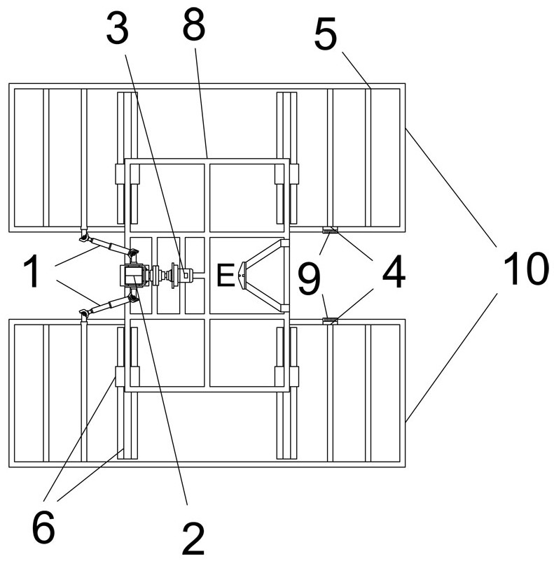
[0048] like Figure 1 to Figure 8 As shown in the figure, a roller cleaning device for a conveying roller table with automatic regulation function includes a transporting bracket 8, the transporting bracket 8 is a square frame structure, one end of the transporting bracket 8 is provided with a regulating device, and two parts of the transporting bracket 8 are provided There is a roller cleaning mechanism on the side;

[0049] The roller cleaning mechanism includes a frame 10 and a reel 4 arranged on the frame 10. The reel 4 includes an unwinding shaft 401 and a winding shaft 402, and the unwinding shaft 401 and the winding shaft 402 are respectively arranged on both sides of the frame 10. , a cleaning roll is wound between the unwinding shaft 401 and the winding shaft 402, and the cleaning roll is exported from the unwinding shaft 401, wraps the bottom surface of the frame 10 and is connected with the winding shaft 402;

[0050] The control device includes a drive motor 3, a do...

Embodiment 2

[0056] The cleaning mechanism is optimized to increase the smoothness of the cleaning process:

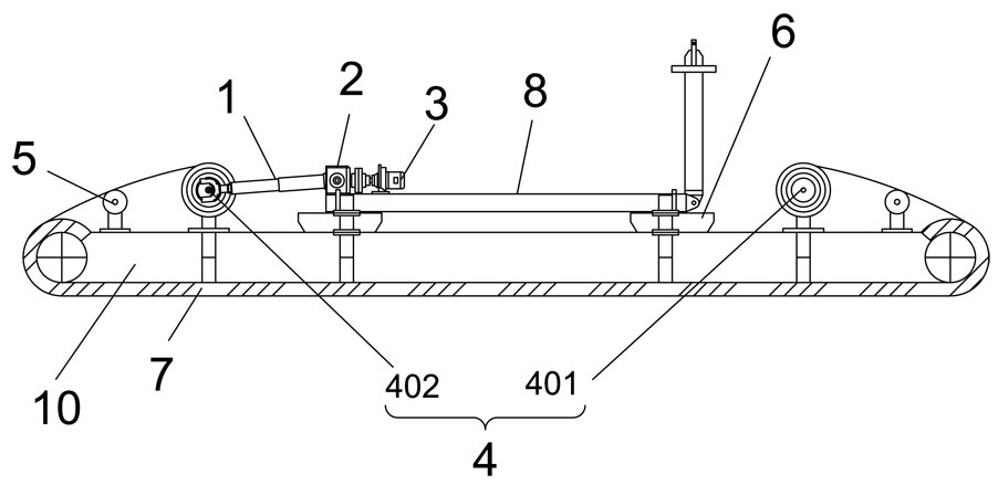
[0057] like figure 2 As shown, the rear side of the unwinding shaft 401 and the front side of the rewinding shaft 402 are symmetrically provided with deflector rollers 5 along the center line of the frame 10. The deflector rollers 5 are used to limit the cleaning roll, and the deflector rollers 5 The two ends of the unwinding shaft 401 and the winding shaft 402 are respectively provided with brackets. The deflecting roller 5 , the unwinding shaft 401 and the winding shaft 402 are rotatably connected with the brackets, and the brackets are fixedly connected with the frame 10 .

[0058] The frame 10 is a square frame, and the two ends of the frame 10 are column-shaped strips. The bottom of the frame 10 is provided with a felt pad 7 for increasing friction. The felt pad 7 is fixed to the bottom surface and both ends of the frame 10. The pad 7 is arranged on the inner side of the cle...

Embodiment 3

[0061] In order to avoid the confusion of the cleaning position of the cleaning roll caused by the two-way movement, set the limit device 9:

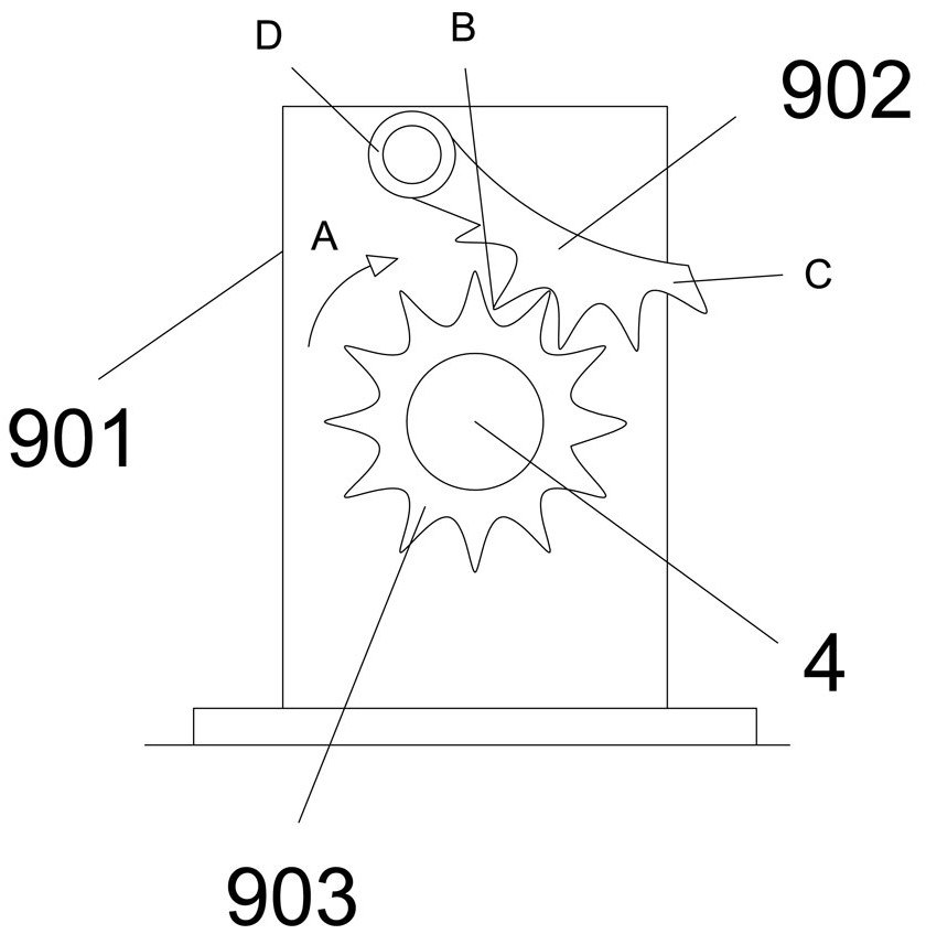
[0062] The unwinding shaft 401 and the rewinding shaft 402 are both provided with a one-way limit device 9, the one-way limit device 9 includes a connecting plate 901 and a gear mechanism, the gear mechanism includes a limit card 902 and a gear 903, the The gear 903 is respectively fixed with the unwinding shaft 401 and the winding shaft 402, the limit card 902 is rotatably connected with the connecting plate 901, the connecting plate 901 is a square plate, and the connecting plate 901 is fixed with the frame 10;

[0063] The limit card 902 is a meniscus-shaped structure, the middle of the limit card 902 is provided with teeth, the limit card 902 meshes with the gear 903 through the teeth, and the limit card 902 limits the position when the gear 903 is reversed.

[0064] like image 3 As mentioned above, in the figure, A represents the...


PUM


Abstract

The roller cleaning device with the automatic regulation and control function for the conveying roller way comprises an allocation and transportation support, a regulation and control device is arranged at one end of the allocation and transportation support, and roller cleaning mechanisms are arranged on the two sides of the allocation and transportation support respectively; the regulation and control device comprises a driving motor, a double-output-shaft speed reducer and telescopic universal couplings, an output shaft of the driving motor is connected with the double-output-shaft speed reducer, and two output shafts of the double-output-shaft speed reducer are connected with the roller cleaning mechanism through the telescopic universal couplings respectively; a width adjusting mechanism is arranged on the lower portion of the dispatching support, and the dispatching support is connected with the frame through the width adjusting mechanism. The driving motor is connected with a motor controller which is used for controlling the driving motor to be powered on for operation. The conveying roller way cleaning device is provided with the roller cleaning mechanism used for fixing the cleaning roll, the roller cleaning mechanism is provided with the regulation and control device to achieve automatic one-way replacement of the cleaning roll, the position of the working face is adjusted in combination with the width adjusting mechanism, the safety of conveying roller way cleaning operation is improved, and the efficiency of conveying roller way cleaning operation is improved.

Description

technical field [0001] The invention relates to the field of roller table cleaning of aluminum processing hot rolling mills, in particular to a roller cleaning device for conveying roller tables with automatic regulation function. Background technique [0002] During the operation of the transfer roller table of the hot rolling mill train, impurities will remain on the surface of the transfer roller table, resulting in metal bonding during the transfer process. In order to prevent metal bonding during the transfer process and improve the surface quality of the product, it is necessary to use a roller cleaner to The conveying rollers are ground and cleaned. [0003] The existing fixed roller cleaner includes four pressing rollers and a cleaning plane. The four pressing rollers are symmetrically distributed, and sandpaper is wrapped outside the cleaning plane. The sandpaper is fixed by the four pressing rollers. First, manually rotate the pressure roller to make the four pres...

Claims


Application Information

Patent Timeline
IPC IPC(8): B65G45/10B24B21/02B24B21/18B24B27/033
CPCB65G45/10B24B27/033B24B21/02B24B21/18
Inventor 邓艳超孙文朋李伟坡何延武刘杰邵三勇
Owner 河南义瑞新材料科技有限公司
Why Eureka
Try Eureka