Check patentability & draft patents in minutes with Patsnap Eureka AI!

Rotor structure of synchronous motor

A technology of rotor structure, synchronous motor, applied in the direction of magnetic circuit shape/style/structure, synchronous motor with static armature and rotating magnet, electrical components, etc., can solve the problems of difficult magnets, reduced accuracy, not a solution, etc.

Pending Publication Date: 2022-03-29
SANYO DENKI CO LTD
View PDF2 Cites 0 Cited by
  • Summary
  • Abstract
  • Description
  • Claims
  • Application Information

AI Technical Summary

Problems solved by technology

In addition, since the elliptical shape does not have a bottom surface as a processing reference, it is difficult to apply methods suitable for mass production, such as grinding with a grindstone, to deformed elliptical magnets.
Therefore, it is actually difficult to use the magnets invented in the above-mentioned documents due to the fact that the manufacturing difficulty of the permanent magnet itself becomes high, and although it is possible to produce deformed elliptical magnets by methods such as wire cutting, it is difficult to ensure productivity.
[0017] In addition, in the above-mentioned technology, when the permanent magnet is pasted on the shaft or the rotor core, it is difficult to determine the standard for pasting the permanent magnet.
Therefore, a reduction in accuracy occurs due to misalignment at the time of bonding, which adversely affects the cogging torque and torque ripple of the completed synchronous motor.
In order to prevent this situation, it is conceivable to accept the reduction of productivity and carry out precise positioning, but this is not a realistic solution

Method used


Image

  • Rotor structure of synchronous motor
  • Rotor structure of synchronous motor
  • Rotor structure of synchronous motor

Examples


Embodiment approach 2

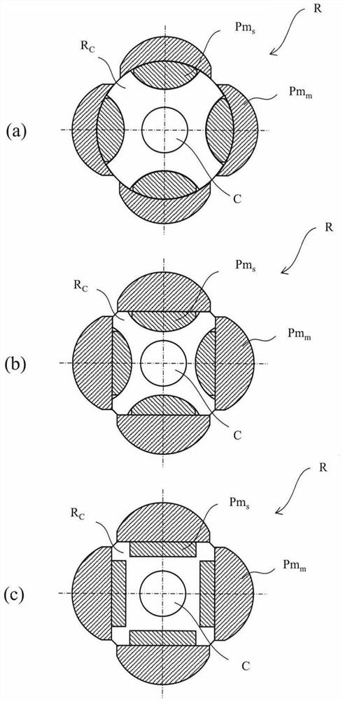
[0062] exist figure 1 In the second embodiment shown in (b), unlike the first embodiment, the rotor core R c is roughly square in shape.

[0063] Rotor core R attached to main shaft C of synchronous motor M c It has a substantially square shape, and each of its four sides constitutes a straight line perpendicular to a line extending from the main axis C in the radial direction. On each of these sides, a total of four main magnets Pm constituting the permanent magnets Pm are joined around the main axis C at each side, that is, every 90 degrees. m . Main magnet Pm m It has a generally known cross-section D shape, and has a rotor core R c The four sides of the inner peripheral side of the contact. Here, as described above, these main magnets Pm m The width is designed to expand to the extreme position.

[0064] in the rotor core R c The main magnet Pm m The inner peripheral surface side, that is, the back side of the m A concave portion, etc., which is convex in the di...

Embodiment approach 5

[0079] figure 2 Embodiment 5 shown in (b) with figure 2 Similarly to Embodiment 4 shown in (a), the main magnet Pm of the permanent magnet Pm is m is related to the rotor core R c An example of a concentric ring-shaped magnet.

[0080] In this method, in the rotor core R c The main magnet Pm m The inner peripheral surface side, ie, the back, is provided with independently convex recesses or holes (recesses, etc.). These concave portions and the like include each main magnet Pm m The inner peripheral surface side of which is aligned with the outer peripheral surface side of which the arc is drawn with respect to the main axis, and the inner peripheral surface side that is formed as a straight line perpendicular to the line extending in the radial direction from the main axis C. A total of four auxiliary magnets Pm are embedded and arranged in each concave portion, etc. s . That is, a total of four auxiliary magnets Pm s Around the main axis C every 90 degrees with th...


PUM


Abstract

The invention provides a rotor structure of a synchronous motor. A rotor structure of a synchronous motor includes: a stator; and a rotor disposed on the inner circumferential side of the stator and capable of rotating, the rotor including a rotor core fixed to a rotating shaft and permanent magnets provided on the outer circumferential side of the rotor core, the permanent magnets provided on the outer circumferential side of the rotor core including a main magnet and an auxiliary magnet, the auxiliary magnet is provided so as to be in contact with the outer peripheral side of the rotor core, and the main magnet is provided so as to be in contact with the outer peripheral side of the auxiliary magnet.

Description

[0001] CROSS-REFERENCE TO RELATED APPLICATIONS [0002] This application is based on Japanese Patent Application No. 2020-160993 filed with the Japan Patent Office on September 25, 2020, the entire contents of which are hereby incorporated by reference. technical field [0003] One aspect of the present invention relates to a rotor structure of a synchronous motor. Background technique [0004] In a conventional example, in a synchronous motor, a surface permanent magnet type synchronous motor (Surface Permanent Magnet Synchronous Motor, hereinafter abbreviated as "SPMSM") in which permanent magnets are attached to the surface of the rotor are known as three representative structures of the rotor. model. [0005] In the first mode, C-shaped permanent magnets are attached to the outer circumference of the shaft or rotor core having a circular cross section. The C-shaped permanent magnet is processed into a shape surrounded by a plurality of different radii of curvature incl...

Claims


Application Information

Patent Timeline
Patent Type & Authority Applications(China)
IPC IPC(8): H02K1/278H02K21/14
CPCH02K1/278H02K21/14H02K2213/03H02K1/2781H02K29/03H02K1/246H02K21/028H02K1/02H02K1/2766H02K2201/06H02K2201/09
Inventor 堀内学长田启亮
Owner SANYO DENKI CO LTD
Features
  • R&D
  • Intellectual Property
  • Life Sciences
  • Materials
  • Tech Scout
  • Unparalleled Data Quality
  • Higher Quality Content
  • 60% Fewer Hallucinations
Learn More